Wireless link fault handling method based on carrier aggregation and user equipment

A wireless link failure, user equipment technology, applied in the field of communication, can solve problems such as wireless connection reconstruction

Inactive Publication Date: 2011-03-30
ZTE CORP
View PDF4 Cites 36 Cited by
  • Summary
  • Abstract
  • Description
  • Claims
  • Application Information

AI Technical Summary

Problems solved by technology

[0008] The present invention is proposed to solve the problem of triggering wireless connection re-establishment in the related art when some carriers have a wireless link failure in carrier aggregation. Therefore, the main purpose of the present invention is to provide a wireless link failure processing method based on carrier aggregation and user equipment to address at least one of the above

Method used


Image

  • Wireless link fault handling method based on carrier aggregation and user equipment
  • Wireless link fault handling method based on carrier aggregation and user equipment
  • Wireless link fault handling method based on carrier aggregation and user equipment

Examples


example 1

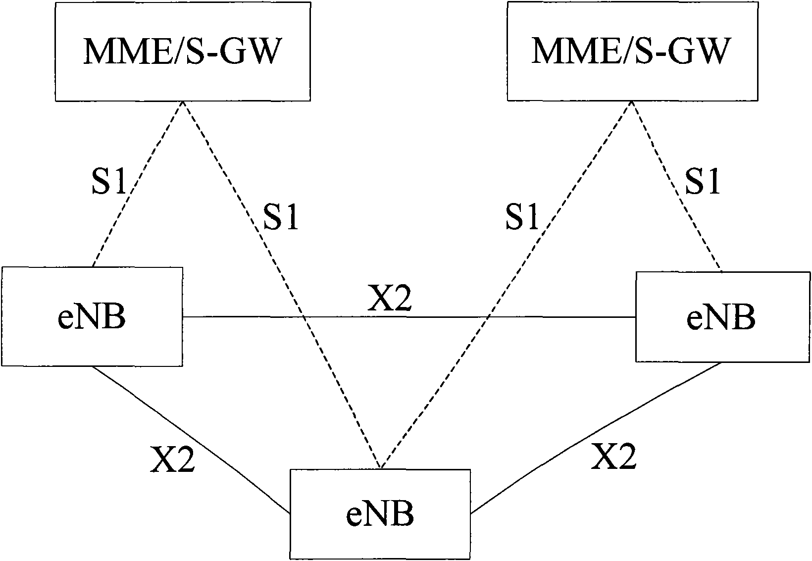
[0039] The example application scenario is an LTE Advance system, and its network architecture is as follows: figure 1 shown. It is assumed that the cell under the jurisdiction of the base station is a carrier aggregation cell, and the UE is in an idle state in the carrier aggregation cell. The component carriers contained in the carrier aggregation cell are in Band 1 (Band 1), there are three consecutive component carriers CC(f1), CC(f2), and CC(f3) in the downlink, and there are also three consecutive carrier CCs in the uplink ( f4), CC(f5), CC(f6), it should be noted that in this example, the frequency information of each component carrier is used to identify the component carrier, but the present invention does not limit the way of carrier identification. The three downlink carriers all send system messages and paging messages.

[0040] At a certain moment, the UE initiates random access on the uplink CC (f4) and downlink CC (f1), and successfully accesses the cell of th...

example 2

[0048] The example application scenario is an LTE Advance system, and its network architecture is as follows: figure 1 shown. It is assumed that the cell under the jurisdiction of the base station is a carrier aggregation cell, and the UE is in an idle state in the carrier aggregation cell. The component carriers contained in the carrier aggregation cell are in Band 1 (Band 1), there are three consecutive component carriers CC(f1), CC(f2), and CC(f3) in the downlink, and there are also three consecutive carrier CCs in the uplink ( f4), CC(f5), CC(f6), it should be noted that in this example, the frequency information of each component carrier is used to identify the component carrier, but the present invention does not limit the way of carrier identification. The three downlink carriers all send system messages and paging messages.

[0049] At a certain moment, the UE initiates random access on the uplink CC (f4) and downlink CC (f1), and successfully accesses the cell of th...

example 3

[0056] The example application scenario is an LTE Advance system, and its network architecture is as follows: figure 1 shown. It is assumed that the cell under the jurisdiction of the base station is a carrier aggregation cell, and the UE is in an idle state in the carrier aggregation cell. The component carriers contained in the carrier aggregation cell are in Band 1 (Band 1), there are three consecutive component carriers CC(f1), CC(f2), and CC(f3) in the downlink, and there are also three consecutive carrier CCs in the uplink ( f4), CC(f5), CC(f6), it should be noted that in this example, the frequency information of each component carrier is used to identify the component carrier, but the present invention does not limit the way of carrier identification. The three downlink carriers all send system messages and paging messages.

[0057] At a certain moment, the UE initiates random access on the uplink CC (f4) and downlink CC (f1), and successfully accesses the cell of th...


PUM


Abstract

The invention discloses a wireless link fault handling method based on carrier aggregation and user equipment. The method comprises the following steps: after detecting that a wireless link fault happens to a carrier allocated by a network side, the user equipment notifies the network side. The user equipment comprises a detection module for detecting whether the wireless link fault happens to the carrier allocated by the network side to the user equipment, and a reporting module for reporting the information of the wireless link fault or the carrier information without wireless link fault to the network side. The invention can enable the network side to know the carrier with wireless link fault so as to carry out consequent handling.

Description

technical field [0001] The present invention relates to the communication field, in particular, to a radio link fault processing method based on carrier aggregation and user equipment. Background technique [0002] The evolved wireless communication system can provide higher transmission rate and shorter transmission delay, and can support the internal access system of The 3rd Generation Partnership Project (The 3rd Generation Partnership Project, referred to as 3GPP) and the 3GPP interface. Mobility between access systems and non-3GPP access systems. [0003] figure 1 It is a schematic diagram of a next-generation network architecture for a long-term evolution (Long Term Evolution, referred to as LTE) system / system architecture evolution (System Architecture Evolution, referred to as SAE), as shown in figure 1 As shown, it includes an evolved radio access network (Evolved Radio Access Network, referred to as E-RAN) and an evolved packet core network (Evolved Packet Core N...

Claims


Application Information

Patent Timeline
Patent Type & Authority Applications(China)
IPC IPC(8): H04W24/04H04W24/10
Inventor 邓云黄亚达施小娟
Owner ZTE CORP
Why Eureka
Try Eureka