
Method, device and system for realizing optimized switching of network

A technology for network optimization and handover preparation. It is applied in network traffic/resource management, electrical components, wireless communication, etc. It can solve problems such as service interruption, data transmission interruption, and lack of clear description, so as to ensure continuity and improve optimization. performance, improve user experience

Active Publication Date: 2014-02-26
HUAWEI TECH CO LTD
View PDF2 Cites 0 Cited by
  • Summary
  • Abstract
  • Description
  • Claims
  • Application Information

AI Technical Summary

Problems solved by technology

[0041] 1. In the existing process, data needs to be cached in E-UTRAN during the handover preparation stage, but in the process, there is no description about MME determining E-UTRAN;
[0042] 2. In the existing process, there is no specific description for the process of establishing a connection between MME and E-UTRAN;
[0043] 3. The existing process does not clearly describe how and when the connection between S101 and S5 is established;
However, in the existing process, when an early path switch is performed in the handover preparation phase (that is, before the UE is handed over to the target network, the PDN GW is bound to the target network), the data transmission in the uplink and downlink directions will be switched to The target network, thus interrupting the data transmission in the Uplink direction, resulting in the interruption of the service at the service layer; moreover, it cannot guarantee the lossless data transmission in the Uplink direction;
[0045] 5. When performing an early path switch, in the existing process, how to establish a default bearer and a dedicated bearer during the switching process is not described;
[0046] 6. In the case of applying policy and charging control (PCC, Policy and Charging Control), how to apply the PCC rule (PCC Rule) to realize the control of the source network and the target network during the handover process of the network anchor (Anchor) ( Such as billing control) and other issues are not described

Method used


Image

  • Method, device and system for realizing optimized switching of network
  • Method, device and system for realizing optimized switching of network
  • Method, device and system for realizing optimized switching of network

Examples


Embodiment 1

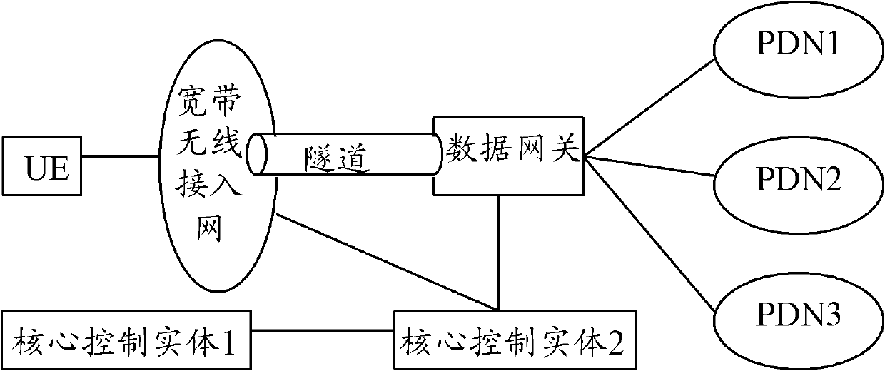
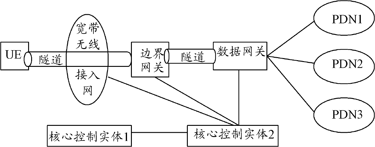
[0128] In this embodiment, it mainly focuses on how the MME selects an evolved base station node (ENB, Evolved Base Node) when the UE is handed over from the Other AN to the E-UTRAN.

[0129] When UE switches from Other AN to E-UTRAN, MME selects ENB and provides two optional solutions.

[0130] The first solution: Other AN configures or obtains the mapping information between the cell ID (Cell ID) and the target network ID (Target ID) corresponding to the E-UTRAN access network. When deciding to switch, the Other AN determines the corresponding cell ID according to the Cell ID. Target ID, and send the Target ID to the MME through the tunnel message of the S101 interface, the MME receives it, and selects the ENB according to the Target ID.

[0131] The second solution: MME configures or obtains the mapping information between Cell ID and Target ID, UE or Other AN sends Cell ID to MME through the tunnel message of S101 interface, and MME determines the corresponding Target ID a...

Embodiment 2

[0150] In this embodiment, the specific process of establishing a connection with the E-UTRAN after the MME determines the corresponding E-UTRAN is mainly described.

[0151] After the MME selects and obtains the SGW information, if it finds that the UE has not established a connection to the selected ENB, and determines that the current process is a handover connection process, it initiates the connection establishment process to the ENB, and completes the configuration and security of the uplink bearer on the user plane. mode configuration.

[0152] Figure 9 It is a schematic flowchart of a method for implementing network optimal handover according to Embodiment 2 of the invention. In this embodiment, after the MME selects the corresponding E-UTRAN, it initiates the establishment of a connection with the E-UTRAN, see Figure 9 , the process includes:

[0153] Step 901, the UE or the network makes a handover decision;

[0154] Step 902, UE sends a connection request mess...

Embodiment 3

[0170] In this embodiment, there are mainly two methods for establishing a dedicated bearer.

[0171] In the first way, dedicated bearers are established one by one. After the default bearer is established, the bearer establishment control entity where the policy and charging enhancement function entity (PCEF, Policy and Charging Enforcement Function) on the network side is located, such as SGW or PDN GW, initiates In the process of establishing a dedicated bearer one by one, the MME processes the received bearer establishment message, and instructs the E-UTRAN not to initiate the establishment process of an air interface bearer by sending a message or adding an indication parameter to the message.

[0172]In the second way, the dedicated bearer information is transmitted in a message, that is, the bearer information to be established is carried in this message, and the dedicated bearer establishment is completed after a Round Trip of a message, and, in the bearer establishment...


PUM


Abstract

The invention discloses a method, a device and a system for realizing the optimized switching of a network. The method comprises the steps of: when user equipment or a source network confirms to initiate the switching preparation to a target network, querying a corresponding target network identification from a configured mapping relation by a mobility management entity according to a received cell identification so as to confirm an access node of the target network; establishing the connection to a target network service gateway and instructing or instructing, by the service gateway, a packet data network gateway to process the uplink and downlink data channels of a user interface; after accomplishing the connection to the service gateway, initiating a resource reserving request of the access node of the target network by the mobility management entity, and instructing not to establish the air interface connection; and after accomplishing the switching preparation, instructing, by the mobility management entity or the service gateway, the packet data network gateway to switch the uplink and downlink data channels of the user interface to the target network. Through the application of the invention, the continuity of the service can be ensured and the user experience can be improved when the user equipment is switched from the source network to the target network.

Description

[0001] This application is a divisional application of the original application with the application date of November 9, 2007, the application number "200710169584.5", and the invention titled "A Method, Equipment and System for Realizing Network Optimal Handover". technical field [0002] The invention relates to network switching technology, in particular to a method, device and system for realizing network optimal switching. Background technique [0003] Traditional telecommunication networks, especially wireless communication networks, such as Global System for Mobile Communications (GSM, Global System for Mobile communications) and Universal Mobile Telecommunications System (UMTS, Universal Mobile Telecommunications System), have the advantages of rich business types and strong network control capabilities. , has been widely used. With the continuous development and improvement of network technology, users have higher requirements for the rate of data services. However,...

Claims


Application Information

Patent Timeline
Patent Type & Authority Patents(China)
IPC IPC(8): H04W28/26H04W36/14H04W36/18H04W76/02
Inventor 帅扬来刘海朱文若黄龙贵
Owner HUAWEI TECH CO LTD
Learn More