Combined forging die and manufacturing method thereof

A combined, forging die technology, used in forging/pressing/hammering machinery, manufacturing tools, heat treatment equipment, etc., can solve problems such as difficulty and poor forging die stability, and achieve extended life, small welding deformation, and processing difficulty. low effect

Inactive Publication Date: 2011-04-06
SHANDONG DONGYI MACHINERY MFG
View PDF6 Cites 6 Cited by
  • Summary
  • Abstract
  • Description
  • Claims
  • Application Information

AI Technical Summary

Problems solved by technology

However, the disadvantage of this patent is that: it is recorded in the patent document that the inlay mold i

Method used


Image

  • Combined forging die and manufacturing method thereof
  • Combined forging die and manufacturing method thereof

Examples


Embodiment 1

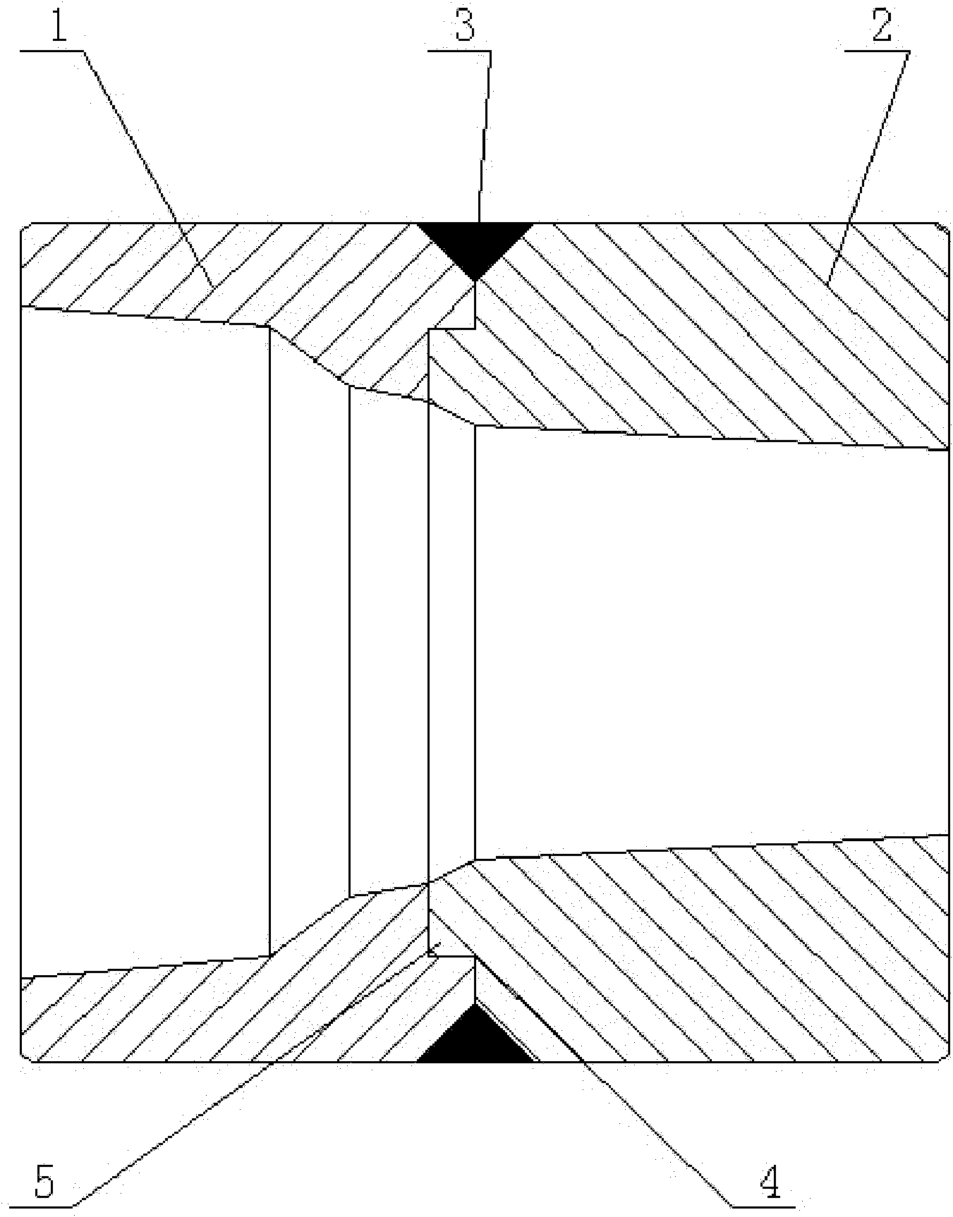
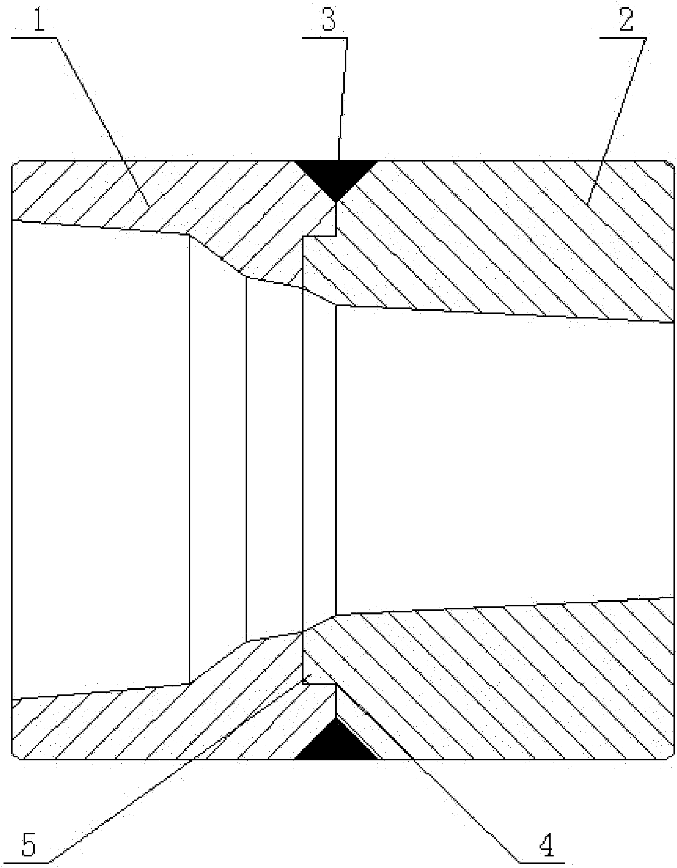
[0032] A combined forging die comprises a die head 1 and a die body 2. The outer edge of the lower end surface of the die head 1 is fixedly connected to the outer edge of the upper end face of the die body by welding. The original overall forging die was set up as upper and lower parts, and the two parts were connected together by welding, which not only maintained the mechanical strength of the overall forging die, but also made it easier and faster to replace parts of the forging die.

Embodiment 2

[0034] A combined forging die as described in Example 1, the difference is that: the lower end surface of the die head 1 is provided with an outer annular boss 4, and the upper end surface of the mold body 2 is provided with an inner annular boss 5. The heights of the inner annular boss 5 and the outer annular boss 4 are the same; the inner diameter of the outer annular boss 4 is adapted to the outer diameter of the inner annular boss 5; the outer annular boss 4 The outer edge of the mold body is fixedly connected with the outer edge of the upper end surface of the mold body by welding.

[0035] On the opposite surface of the die head 1 and the die body 2, a boss is correspondingly arranged, so that the die head and the die body are installed tightly, and problems such as displacement and deformation are avoided; the die head and the die body are fixedly connected by welding, which increases the The stability of the forging die; only welding the edge part is the prerequisite f...

Embodiment 3

[0037] A method for manufacturing the combined forging die described in embodiment 2, the specific steps are as follows:

[0038] 1) The lower end surface of the die head 1 is provided with an outer annular boss 4, and the upper end surface of the mold body 2 is provided with an inner annular boss 5, and the height of the inner annular boss 5 and the outer annular boss 4 is the same; The inner diameter of the outer annular boss 4 is compatible with the outer diameter of the inner annular boss 5;

[0039] 2) The operator uses a lathe to process grooves on the outer edge of the outer annular boss 4 and the outer edge of the upper end surface of the mold body 2 respectively, and the depth of the groove is 13% of the thickness of the forging die;

[0040] 3) Heat the die head 1 to 240-280°C, put the heated die head 1 on the upper end surface of the mold body 2 at room temperature, and the groove on the outer edge of the outer annular boss 4 and the upper end surface of the mold bo...


PUM


Abstract

The invention relates to a combined forging die and a manufacturing method thereof. The forging die comprises a die head and a die body, wherein the outer edge of the lower end face of the die head is fixedly connected with the outer edge of the upper end face of the die body in a welded way. The invention has the following advantages that the defect that an integral forging die cannot be used repeatedly can be effectively overcome; the cost of die manufacturing is reduced; the forging die can be changed just by separately detaching the worn die head or die body, without changing the whole forging die, thereby meeting the requirement of energy saving and emission reduction; processing difficulty is lower, processing time is short, the overall utilization of the forging die is improved; the service life of the forging die is prolonged; and therefore, the production efficiency is improved further.

Description

technical field [0001] The invention relates to a combined forging die and a preparation method thereof, belonging to the technical field of forging dies. Background technique [0002] Most of the forging dies used today are monolithic structures. During the forging process, due to the high impact force of the punch press, after a period of use, the upper inner edge of the forging die will be damaged, which will affect the forging of mechanical parts. For example, in the field of shaft coupling processing, it is necessary to use a forging die with precise dimensions to process the shaft adapter of the shaft coupling. Worn forging dies cannot be used repeatedly, but new forging dies have a long processing cycle, high difficulty and high cost, which has become one of the important factors affecting the efficiency of forging production. Therefore, effectively prolonging the service life of forging dies has become a technical problem to be solved urgently to improve the quality...

Claims


Application Information

Patent Timeline
IPC IPC(8): B21J13/02B23P15/24C21D9/00
Inventor 李恒利尹承恩
Owner SHANDONG DONGYI MACHINERY MFG
Why Eureka
Try Eureka