Biaxial multilayer cloth warp knitting machine

A biaxial, warp knitting machine technology, applied in flat warp knitting machines, warp knitting, textiles and papermaking, etc., can solve the problem of speeding up the working speed of cloth surface splitting needle parts, speeding up servo motors, and affecting the quality of finished cloth and other issues, to achieve the effect of easy modular control, quality assurance, and convenient control

Active Publication Date: 2012-11-28
CHANGZHOU DIBA TEXTILE MACHINERY
View PDF0 Cites 0 Cited by
  • Summary
  • Abstract
  • Description
  • Claims
  • Application Information

AI Technical Summary

Problems solved by technology

[0002] A power drive device is designed in the existing biaxial warp knitting machine, that is, a servo motor is provided, which not only drives the work of the cloth surface dividing needle parts through the servo motor, but also drives the cloth surface of the warp knitting machine. It is difficult to control the speed of cloth surface transmission according to actual needs. When the speed of cloth surface transmission needs to be accelerated, the rotation speed of the servo motor needs to be increased, which will speed up the working speed of the cloth surface dividing needle parts at the same time and affect the finished product. cloth quality

Method used


Image

  • Biaxial multilayer cloth warp knitting machine
  • Biaxial multilayer cloth warp knitting machine
  • Biaxial multilayer cloth warp knitting machine

Examples


Embodiment Construction

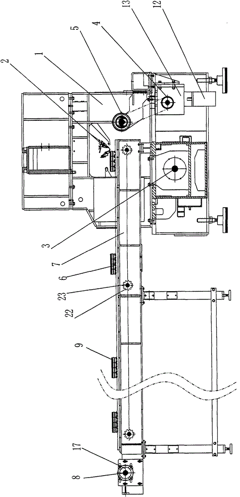
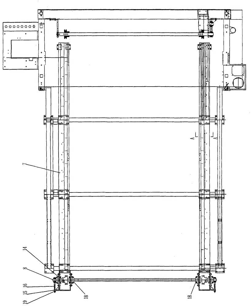
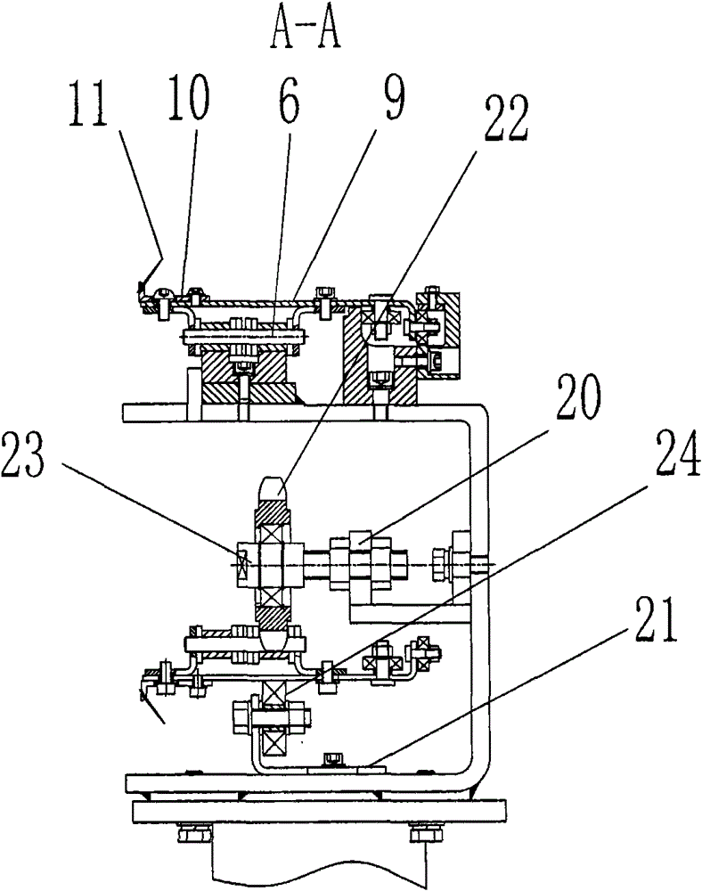
[0013] refer to Figure 1 to Figure 3 A kind of biaxial multi-layer cloth warp knitting machine shown, it comprises biaxial cloth face splitting needle part lathe bed 1, cloth face splitting needle part 2 and cloth face conveying device, described biaxial cloth face The bed of the surface dividing needle part 1 is provided with a biaxial machine head bed main shaft 3 for controlling the work of the surface dividing needle part 2, and the cloth surface conveying device includes a driving device and a speed reducer for sprocket pulling Synchronous pulley 4, rotary sprocket 5, double-row chain 6 for sprocket pulling and chain box 7, reducer for sprocket pulling synchronous pulley 4 is connected to rotary sprocket 5 through a synchronous belt, and rotary sprocket 5 is set On the tail sprocket pulling shaft 8 on the left and right sides of the chain box body 7, the double row chain 6 for sprocket pulling is arranged on the rotary sprocket 5, and the outside of the double row chain ...


PUM


Abstract

The invention discloses a biaxial multilayer cloth warp knitting machine. The warp knitting machine comprises a biaxial cloth cover separating needle component lathe bed, a cloth cover separating needle component and a cloth cover conveying device, wherein the biaxial cloth cover separating needle component lathe bed is provided with a biaxial machine head lathe bed main shaft for controlling work of the cloth cover separating needle component; the warp knitting machine is characterized in that: the cloth cover conveying device comprises a driving device, a reducer synchronous pulley for drawing a chain wheel, a rotary chain wheel, a duplex chain for drawing the chain wheel and a chain box; the reducer synchronous pulley for drawing the chain wheel is connected with the rotary chain wheelthrough a synchronous pulley; the rotary chain wheel is arranged on machine tail chain wheel drawing shafts on the left side and the right side of the chain box; the duplex chain for drawing the chain wheel is arranged on the rotary chain wheel and a pin plate is connected with the outer side of the duplex chain for drawing the chain wheel; copper pin blocks are arranged on the two sides of the pin plate respectively; and separating needles are arranged outside the copper pin blocks. The warp knitting machine has the advantage that the conveying speed of a cloth cover of the warp knitting machine can be conveniently controlled.

Description

technical field [0001] The invention relates to a biaxial warp knitting machine, in particular to a biaxial multilayer cloth warp knitting machine with a separate cloth surface conveying device. Background technique [0002] A power drive device is designed in the existing biaxial warp knitting machine, that is, a servo motor is provided, not only to drive the work of the cloth surface dividing needle parts through the servo motor, but also to drive the cloth surface of the warp knitting machine. It is difficult to control the speed of cloth surface transmission according to the actual needs. When the speed of cloth surface transmission needs to be accelerated, the speed of the servo motor needs to be increased, which will speed up the working speed of the cloth surface dividing needle parts at the same time and affect the finished product. The quality of the cloth. Contents of the invention [0003] The object of the present invention is to provide a biaxial multi-layer ...

Claims


Application Information

Patent Timeline
Patent Type & Authority Patents(China)
IPC IPC(8): D04B23/00D04B27/34
Inventor 谈昆伦陈震陈亚飞凌伯明陈龙谈良春
Owner CHANGZHOU DIBA TEXTILE MACHINERY
Why Eureka
Try Eureka