High-voltage axial flow fan

A flow fan and high-pressure shaft technology, applied in the field of high-pressure axial flow fans, can solve the problem of low fan pressure, achieve the effects of improving efficiency, increasing volume flow, and reducing losses

Inactive Publication Date: 2011-04-06
陈新
View PDF6 Cites 14 Cited by
  • Summary
  • Abstract
  • Description
  • Claims
  • Application Information

AI Technical Summary

Problems solved by technology

It can be seen from this that the pressure of the existing fan is not high. Therefore, it is necessary to propose a high-pressure axial flow fan

Method used


Image

  • High-voltage axial flow fan
  • High-voltage axial flow fan
  • High-voltage axial flow fan

Examples


Embodiment 1

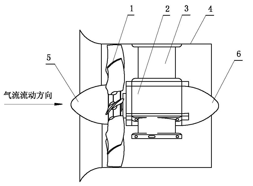
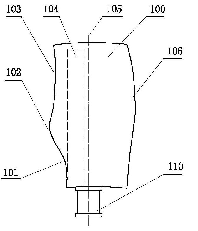
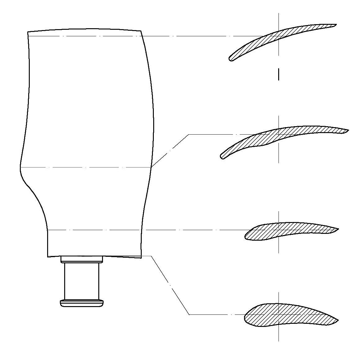
[0025] see figure 1 and figure 2 , the high-pressure axial flow fan of the present invention has an impeller device and a drive motor device. The impeller device 1 includes a hub on which a plurality of bird-wing-shaped blades are installed, and a conical shroud 5 is installed on the inlet end of the hub. , the hub is installed on the drive shaft of the drive motor device 2; the drive motor device is installed in the center of a cylindrical rectifying air duct 4, fixed to the inner wall of the cylindrical rectifying air duct by a plurality of pull arms 3 , the rear portion of the drive motor device is provided with a conical shroud 6; the bird-wing blade includes a blade body 100 and a petiole 110, and the lower part of the air inlet side of the blade body is provided with a wing-shaped leaf nest area 101, and the blade body A wing-shaped blade convex area 102 is set in the middle of the air inlet side, and a wing-shaped blade concave area 103 is set in the upper part of the...

Embodiment 2

[0036] The high-pressure axial fan in this embodiment is an improvement on the basis of Embodiment 1. The technical content disclosed in Embodiment 1 will not be described repeatedly, and the content disclosed in Embodiment 1 also belongs to the content disclosed in this embodiment.

[0037] see figure 1 , Figure 6 , Figure 7 , in the present embodiment, described drive motor device 2 comprises stator 202 and rotor 201, the length of the silicon steel sheet group in the stator is 92 millimeters, and the outer diameter of the outer shell of stator is 128 millimeters, in order to increase flow area, stator There is no cooling fin on the outside, and the total length of the stator is 210 mm. The volume of the driving motor disclosed in this embodiment is obviously smaller than that of the driving motor used in the axial flow fan with the same power. In this embodiment, the diameter-to-length ratio of the stator in the driving motor device is 128:210. According to the change ...

Embodiment 3

[0041] see Figure 8 , Figure 9 , Figure 10 , the high-pressure axial flow fan of the present invention has an impeller device, a drive motor device, and a front-stage fan. The impeller device 300 in the front-stage fan includes a hub on which a plurality of bird-wing-shaped blades are installed. The hub is installed on the drive shaft of the driving motor device; the driving motor device is installed at the center of a cylindrical rectifying air duct, fixed to the inner wall of the cylindrical rectifying air duct through a plurality of pull arms, and the cylindrical rectifying air duct The air inlet of the rectifying air duct is provided with a conical shroud; there is a rear-stage fan, and the impeller device 400 in the rear-stage fan includes a hub on which a plurality of bird-wing-shaped blades are installed, and the hub Installed on the drive shaft of the drive motor device; the drive motor device is installed in the center of a cylindrical rectifying air duct, and fi...


PUM


Abstract

The invention relates to a high-voltage axial flow fan, comprising an impeller device and a drive motor device. The axial flow fan is characterized in that: the impeller device comprises a hub, wherein a plurality of wing-shaped blades are arranged on the hub, a conical fairing is arranged at the inlet end of the hub, and the hub is arranged on the drive shaft of the drive motor device; the drive motor device is arranged in the center of a flow guidance cylinder and is fixed on the inner wall of the flow guidance cylinder through a plurality of pull arms, and the conical fairing is arranged on the rear part of the drive motor; each wing-shaped blade comprises a blade body and a blade root, a wing-shaped pit area is arranged on the lower part of the inlet edge of the blade body, a wing-shaped convex area is arranged in the middle of the inlet edge of the blade body, and a wing-shaped concave area is arranged on the upper part of the inlet edge of the blade body; an inward convex acceleration area is arranged on the blade basin surface of the blade body; and a rectification area is arranged at the outlet edge of the inside of the blade body.

Description

technical field [0001] The invention relates to a high-pressure axial flow fan. The impeller device of the fan includes a hub on which a plurality of bird-wing-shaped blades are installed. The middle part of the inlet side of the blade is provided with a wing-shaped blade convex area, and the upper part of the air inlet side of the blade body is provided with a wing-shaped blade concave area; the surface of the blade basin of the blade body is provided with an inner convex acceleration area. Background technique [0002] The hub of the mine axial flow main fan in the prior art adopts the fan blade installed in the middle of the hub width. The fan blade is composed of two parts: the blade and the blade root, and the petiole is installed in the middle of the length of the blade section. Obviously, the stability of the blade is poor , it is possible to cause premature damage to the blades and cause fan accidents. Chinese patent 94228382.1 discloses a mine axial flow main fan, ...

Claims


Application Information

Patent Timeline
Patent Type & Authority Applications(China)
IPC IPC(8): F04D29/32F04D29/38
Inventor 陈新
Owner 陈新
Why Eureka
Try Eureka