High-voltage axial flow fan
A flow fan and high-pressure shaft technology, which is applied in the field of high-pressure axial flow fans, can solve the problems of low fan pressure and achieve the effects of improving efficiency, reducing losses, and running smoothly
- Summary
- Abstract
- Description
- Claims
- Application Information
AI Technical Summary
Problems solved by technology
Method used
Image
Examples
Embodiment 1
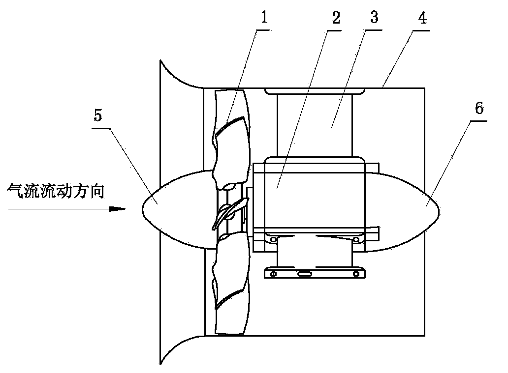
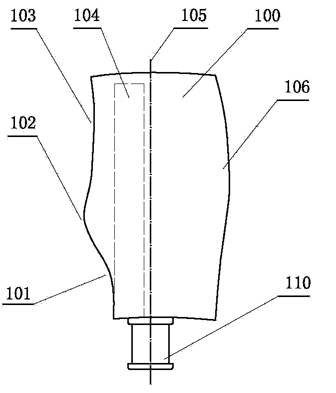
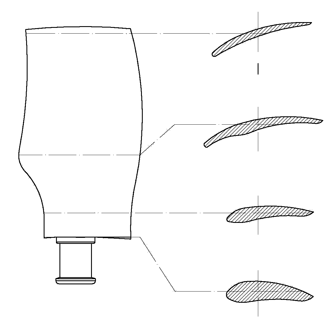
[0025] see figure 1 and figure 2 , the high-pressure axial flow fan of the present invention has an impeller device and a drive motor device. The impeller device 1 includes a hub on which a plurality of bird-wing-shaped blades are installed, and a conical shroud 5 is installed on the inlet end of the hub. , the hub is installed on the drive shaft of the drive motor device 2; the drive motor device is installed in the center of a cylindrical rectifying air duct 4, fixed to the inner wall of the cylindrical rectifying air duct by a plurality of pull arms 3 , the rear portion of the drive motor device is provided with a conical shroud 6; the bird-wing blade includes a blade body 100 and a petiole 110, and the lower part of the air inlet side of the blade body is provided with a wing-shaped leaf nest area 101, and the blade body A wing-shaped blade convex area 102 is set in the middle of the air inlet side, and a wing-shaped blade concave area 103 is set in the upper part of the...
Embodiment 2
[0036] The high-pressure axial fan in this embodiment is an improvement on the basis of Embodiment 1. The technical content disclosed in Embodiment 1 will not be described repeatedly, and the content disclosed in Embodiment 1 also belongs to the content disclosed in this embodiment.
[0037] see figure 1 , Figure 6 , Figure 7 , in the present embodiment, described drive motor device 2 comprises stator 202 and rotor 201, the length of the silicon steel sheet group in the stator is 92 millimeters, and the outer diameter of the outer shell of stator is 128 millimeters, in order to increase flow area, stator There is no cooling fin on the outside, and the total length of the stator is 210 mm. The volume of the driving motor disclosed in this embodiment is obviously smaller than that of the driving motor used in the axial flow fan with the same power. In this embodiment, the diameter-to-length ratio of the stator in the driving motor device is 128:210. According to the change ...
Embodiment 3
[0041] see Figure 8 , Figure 9 , Figure 10 , the high-pressure axial flow fan of the present invention has an impeller device, a drive motor device, and a front-stage fan. The impeller device 300 in the front-stage fan includes a hub on which a plurality of bird-wing-shaped blades are installed. The hub is installed on the drive shaft of the driving motor device; the driving motor device is installed at the center of a cylindrical rectifying air duct, fixed to the inner wall of the cylindrical rectifying air duct through a plurality of pull arms, and the cylindrical rectifying air duct The air inlet of the rectifying air duct is provided with a conical shroud; there is a rear-stage fan, and the impeller device 400 in the rear-stage fan includes a hub on which a plurality of bird-wing-shaped blades are installed, and the hub Installed on the drive shaft of the drive motor device; the drive motor device is installed in the center of a cylindrical rectifying air duct, and fi...
PUM
 Abstract
Description
Claims
Application Information
 - R&D
- Intellectual Property
- Life Sciences
- Materials
- Tech Scout
- Unparalleled Data Quality
- Higher Quality Content
- 60% Fewer Hallucinations
Browse by: Latest US Patents, China's latest patents, Technical Efficacy Thesaurus, Application Domain, Technology Topic, Popular Technical Reports.
© 2025 PatSnap. All rights reserved.Legal|Privacy policy|Modern Slavery Act Transparency Statement|Sitemap|About US| Contact US: help@patsnap.com


