
Anti-leakage treatment method and anti-leakage device at conjunction of pipeline and well wall

A treatment method and anti-leakage technology, applied in the direction of pipes/pipe joints/fittings, pipes, branch pipelines, etc., can solve the problems of difficulty in ensuring tightness, increase construction costs, and high rework costs, so as to improve construction efficiency, The effect of saving construction costs and improving construction efficiency

Active Publication Date: 2011-04-06
CSCEC STRAIT CONSTR & DEV
View PDF4 Cites 2 Cited by
  • Summary
  • Abstract
  • Description
  • Claims
  • Application Information

AI Technical Summary

Problems solved by technology

[0004] The traditional connection method between the pipeline and the inspection well is as follows: first build the inspection well to the elevation of the inner bottom of the pipeline, then install the pipeline, and then build a brick arch on the upper part of the pipeline after the installation is completed, and then build the inspection well to the design elevation. The gaps at the joints of the inspection wells are filled with ordinary mortar, and ordinary mortar is applied inside and outside the inspection wells. After this treatment, the tightness is difficult to guarantee, and leakage is prone to occur, resulting in rework
If seepage occurs at the connection between the pipeline and the inspection well, it will take 2 workers 2 hours to dismantle an inspection well, and 3 workers 5 hours to build another inspection well after the connection is completed. The cost of rework is high, and the construction time is long. increased construction costs

Method used


Image

  • Anti-leakage treatment method and anti-leakage device at conjunction of pipeline and well wall
  • Anti-leakage treatment method and anti-leakage device at conjunction of pipeline and well wall
  • Anti-leakage treatment method and anti-leakage device at conjunction of pipeline and well wall

Examples


specific Embodiment approach 1

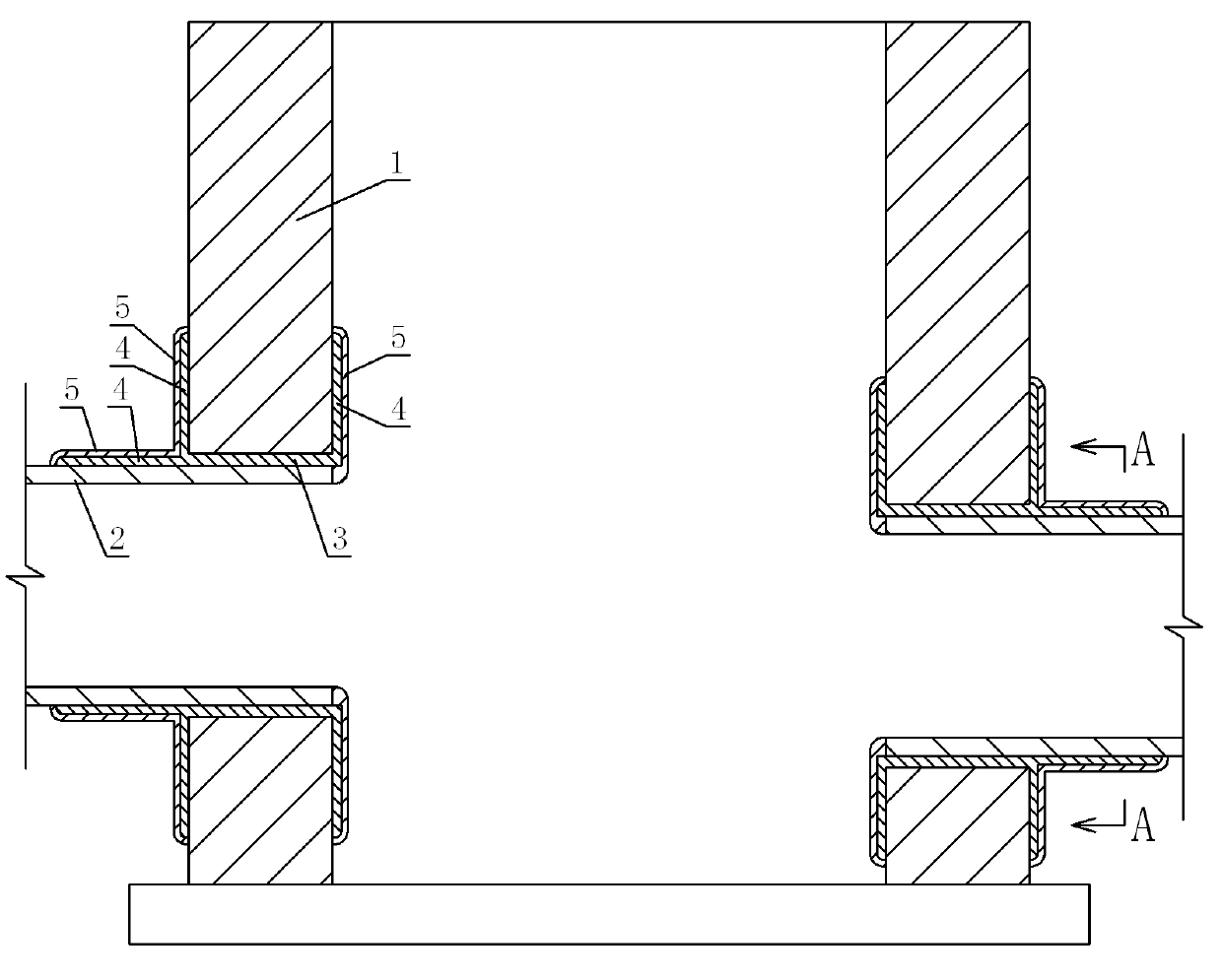
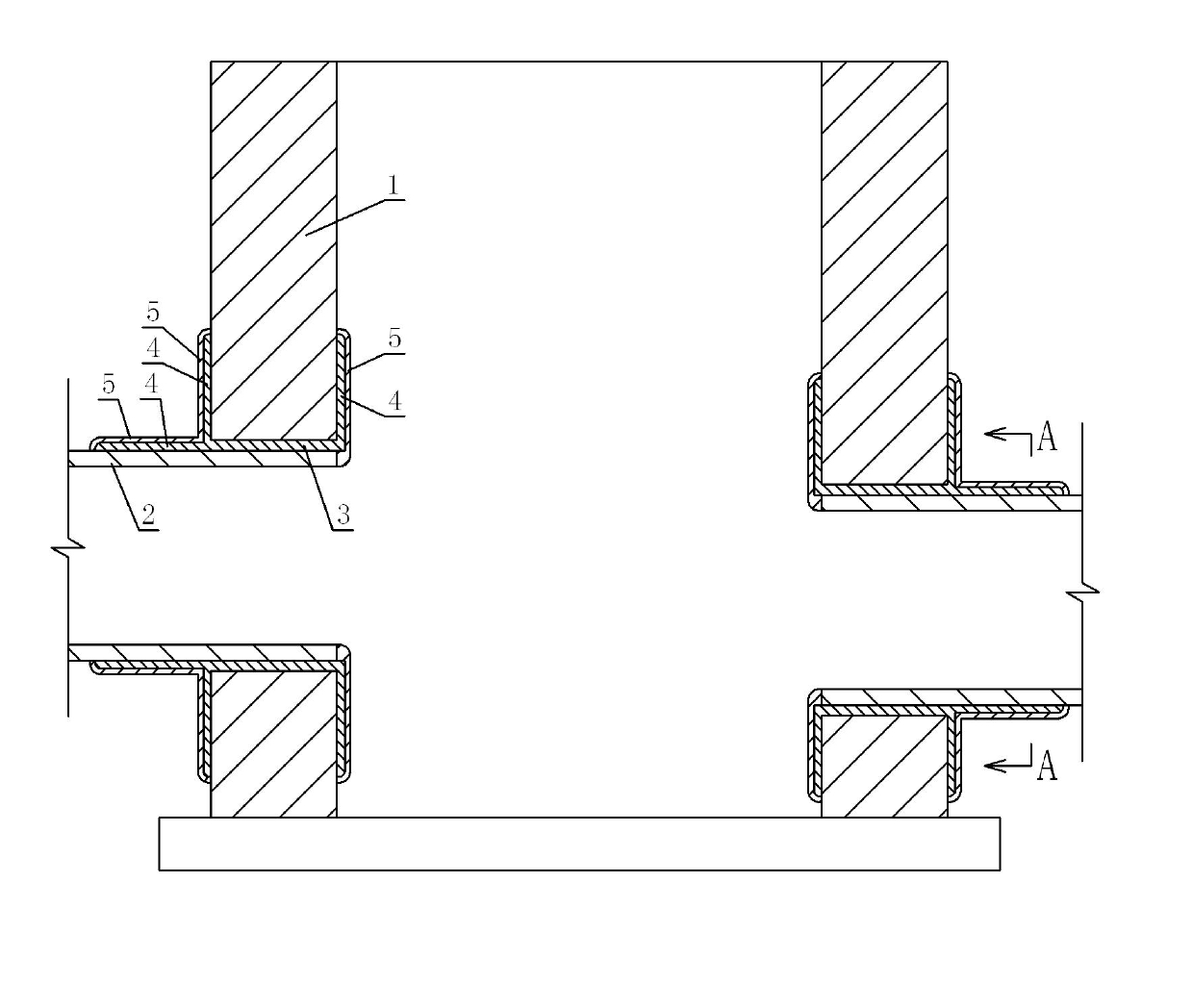
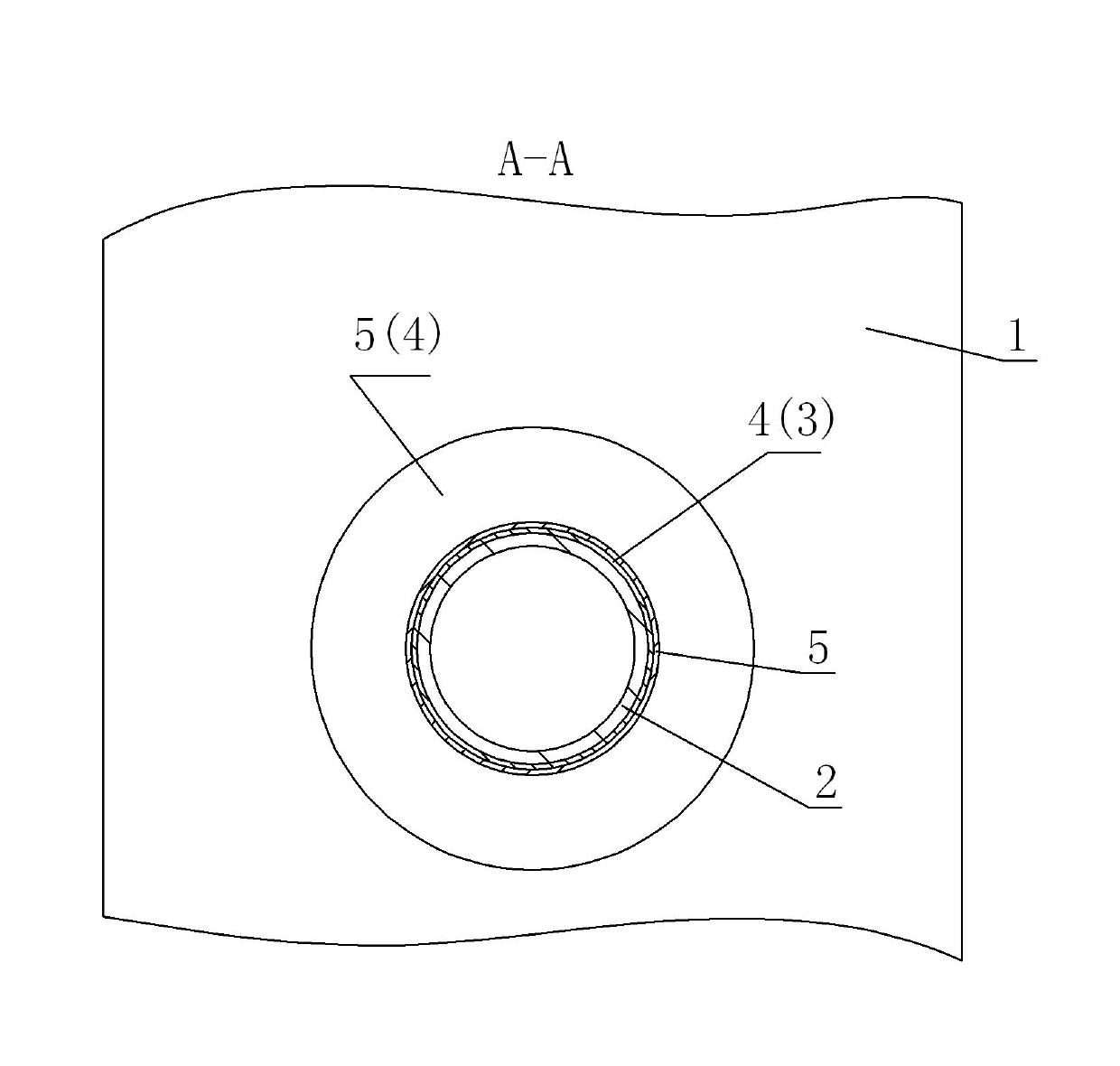
[0017] Such as figure 1 and 2 As shown, the present invention provides an anti-leakage treatment method for the connection between the pipeline and the well wall, which is characterized in that: after the pipeline 2 is installed on the well wall 1, the asphalt is first used to treat the gap between the pipeline 2 and the well wall 1. Fill the installation gap to make the asphalt fill the installation gap between the pipeline 2 and the well wall 1; then brush asphalt around the connection between the pipeline 2 and the well wall 1, so that the pipeline 2, the well wall 1, and the well wall 1 are filled in the installation gap. The asphalt joint layer 3 in the gap and brushing around the joint between the pipeline 2 and the well wall 1 (including the outer wall of the pipeline 2 and the well wall 1 outside the joint between the pipeline 2 and the well wall 1, and the 2 and the inner wall surface of the well wall 1 at the joint of the well wall 1) the asphalt smear layer 4 is co...

specific Embodiment approach 2

[0020] Such as figure 1 and 2 As shown, the present invention provides an anti-leakage device at the joint between the pipeline and the well wall. 2 and the asphalt smear layer 4 around the junction of the well wall 1 and the mortar smear layer 5 covering the outside of the asphalt smear layer 4, the pipeline 2, the well wall 1, the asphalt joint layer 3 and the asphalt smear layer 4 are connected as a whole.

[0021] (3) Examples

[0022] In the municipal road project of the Garden Expo Park, the method of the present invention is used to treat the connection between the pipeline and the inspection well. The specific method is as follows:

[0023] First build the inspection well wall 1 to the inner bottom elevation of the pipeline 2, then install the pipeline 2, and then build a brick arch on the upper part of the pipeline 2 after the installation is completed. After the pipeline 2 is installed and the brick arch masonry is completed, asphalt is used to fill the joints, ...


PUM


Abstract

The invention relates to an anti-leakage treatment method at the conjunction of a pipeline and a well wall, which comprises the following steps: well mounting the pipeline on the well wall, and firstly using asphalt to carry out crack pouring treatment on a mounting crack between the pipeline and the well wall to lead the mounting crack to be filled with the asphalt; then brush-coating the asphalt at the conjunction of the pipeline and the well wall, and leading the pipeline, the well wall, an asphalt crack pouring layer filled in the mounting crack and an asphalt smear layer brush-coated at the conjunction of the pipeline and the well wall to be connected into a whole; and finally using waterproof mortar to carry out mortar finishing treatment on the periphery of the conjunction of the pipeline and the well wall. The invention further provides an anti-leakage device which comprises the asphalt crack pouring layer filled in the mounting crack between the well wall and the pipeline, the asphalt smear layer smeared on the periphery of the conjunction of the pipeline and the well wall and a mortar finishing layer smeared and covered outside the asphalt smear layer. The method and thedevice can greatly reduce the leakage phenomenon at the conjunction of the pipeline and the well wall, effectively reduce the rework phenomenon at the conjunction, improve the construction efficiencyand reduce the construction cost.

Description

technical field [0001] The invention relates to an anti-leakage treatment method and an anti-leakage device for the connection between a pipeline and a well wall. Background technique [0002] Most of the places are pipe joints and the joints between pipes and inspection wells. Most of the pipes used today are electric hot-melt joints. The probability is large, so it often makes it difficult to pass the closed water test. In the closed water test, once leakage occurs at the connection between the pipeline and the inspection well, the connection between the pipeline and the inspection well must be removed for re-construction. The rework cost is high and the construction time is long, especially for large-diameter pipelines and inspection wells. High, greatly increasing the construction cost. [0003] How to ensure the tightness of the connection between the pipeline and the inspection well and ensure that the closed water test is passed at one time is of great significance...

Claims


Application Information

Patent Timeline
IPC IPC(8): F16L41/08
Inventor 何健冯德凯郑洁
Owner CSCEC STRAIT CONSTR & DEV
Learn More