
Autotracking switch type charge pump for phase lock loop
A charge pump, self-tracking technology, applied in the direction of automatic power control, electrical components, adjusting electrical variables, etc., can solve problems such as complex structure, and achieve the effect of reducing circuit complexity, easy implementation, and reducing overall power consumption
Patent Information
- Authority / Receiving Office
- CN · China
- Patent Type
- Applications(China)
- Current Assignee / Owner
- Publication Date
- 2011-04-06
Smart Images
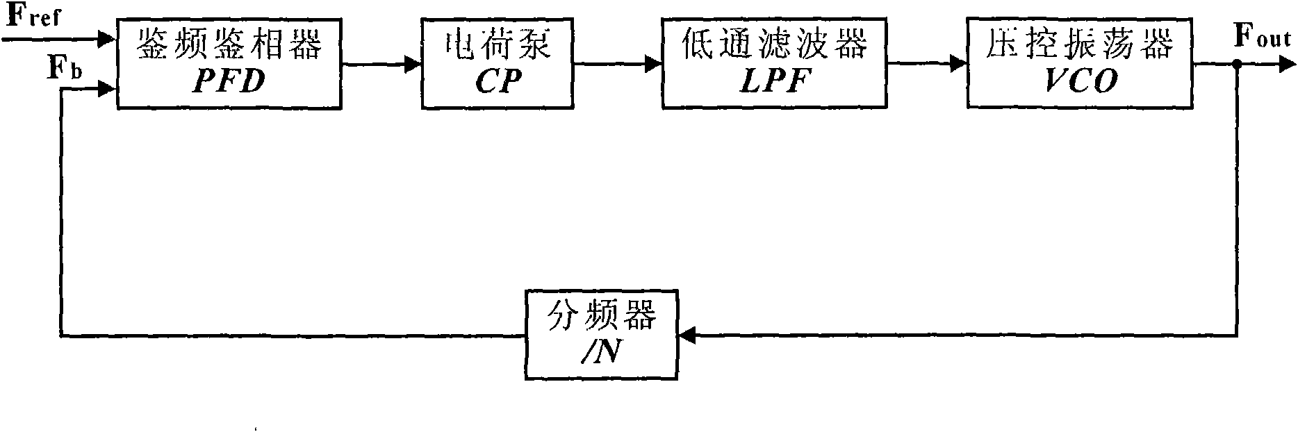
Figure 1 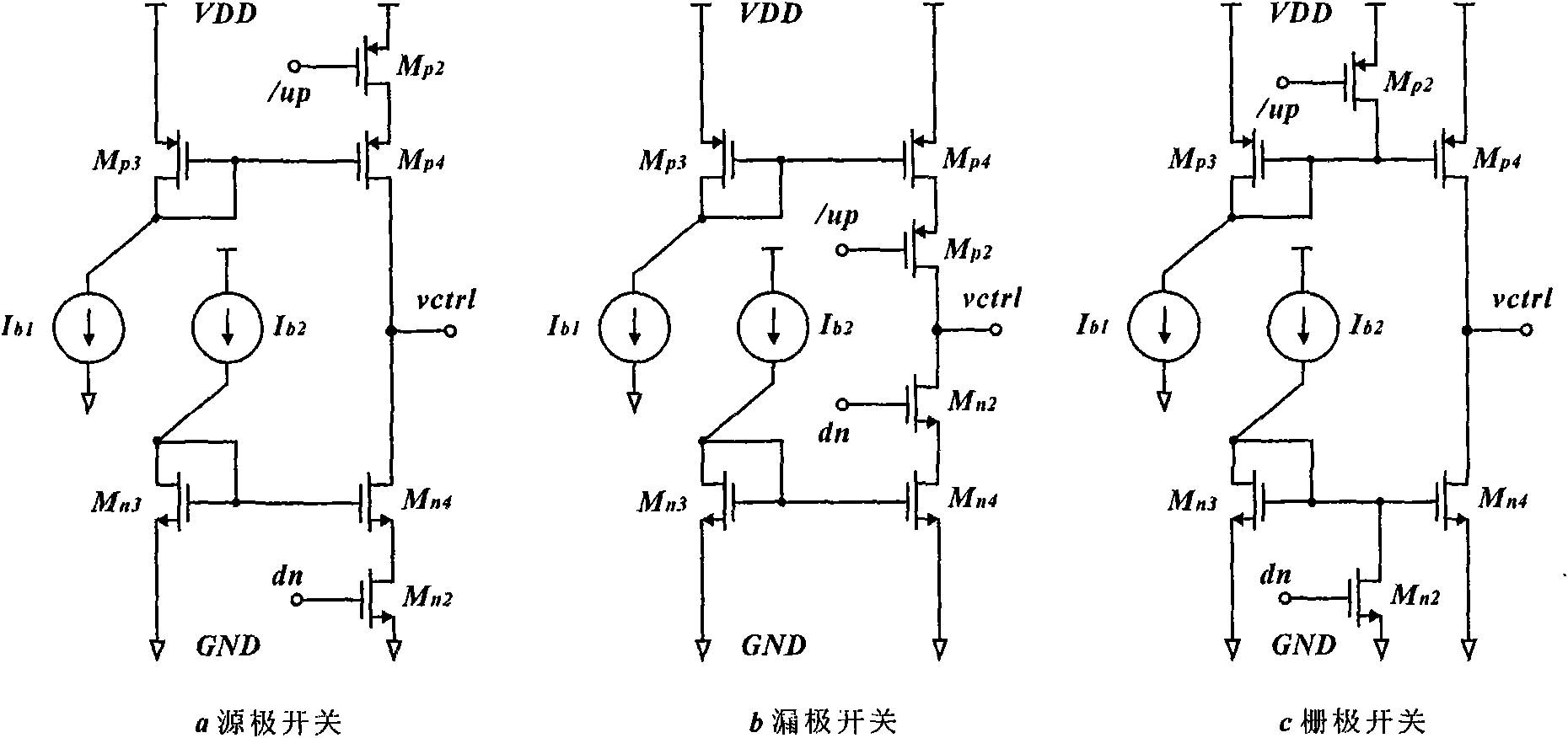
Figure 2 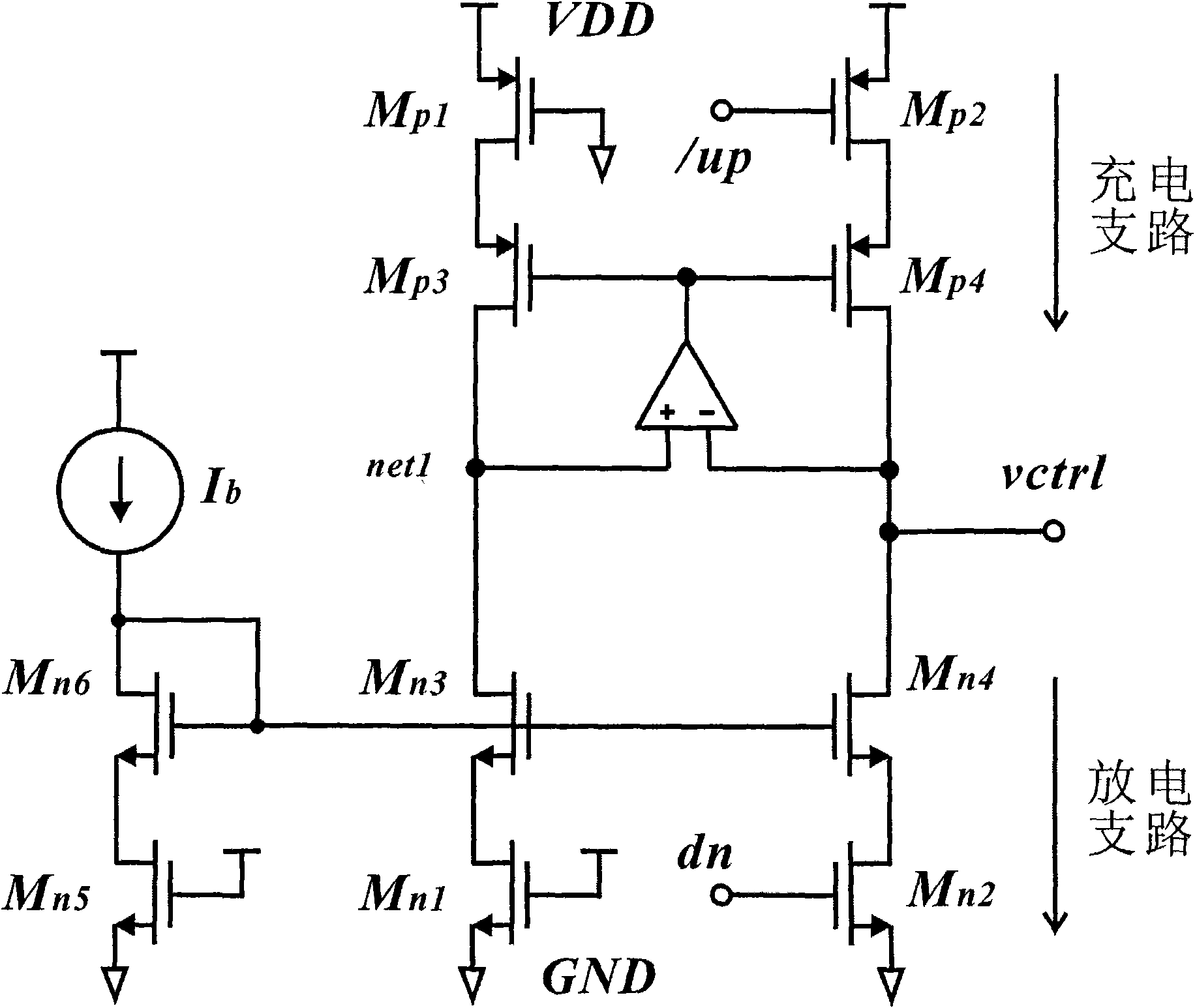
Figure 3
Abstract
Description
technical field
[0001] The invention relates to the technical field of analog integrated circuit design, in particular to a self-tracking switching charge pump used in a phase-locked loop, which can be applied to a charge pump phase-locked loop (Charge Pump Phase-Locking Loop CPPLL). Background technique
[0002] The phase-locked loop (PLL) circuit was first proposed by H. de Bellescize in 1932, because of its excellent diversity, it has been widely used in the fields of electronics and communication. As an important application example, a phase-locked loop can be used to generate an output signal whose frequency is programmable, equal to a rational fractional multiple of a fixed input frequency. This kind of frequency synthesizer based on phase-locked loop is widely used in wireless terminal products. The diversity of the phase-locked loop also makes it applied to the digital system for the recovery of the clock signal and the generation of the clock signal.
[0003] fig...
Examples
Embodiment Construction
[0049] In order to make the object, technical solution and advantages of the present invention clearer, the present invention will be described in further detail below in conjunction with specific embodiments and with reference to the accompanying drawings.
[0050] Figure 5 It is a schematic diagram of an embodiment of the self-tracking switching charge pump used in the phase-locked loop of the present invention. This embodiment is implemented using a CMOS process. The specific circuit description is as follows:
[0051] Self-tracking switching charge pumps for phase-locked loops, including:
[0052] A pull-up circuit, including a PMOS pull-up switch transistor, which receives the control command signal output by the PFD; a PMOS current mirror, which provides charging current; and a PMOS transistor, which is used to match the PMOS pull-up switch transistor.
[0053] A pull-down circuit includes an NMOS pull-down switch transistor to receive the control command signal outp...