Automatic-tracking current type charge pump for phase-locking loop

A charge pump and self-tracking technology, applied in the direction of conversion equipment without intermediate conversion to AC, can solve problems such as complex structure, and achieve the effect of reducing circuit complexity, easy implementation, and reducing overall power consumption

Active Publication Date: 2011-05-25
中科芯未来微电子科技成都有限公司
View PDF0 Cites 6 Cited by
  • Summary
  • Abstract
  • Description
  • Claims
  • Application Information

AI Technical Summary

Problems solved by technology

(2) The structure is complex, and the traditional charge pump structure needs to provide bias current and feedback amplifier to meet the performance requirements

Method used


Image

  • Automatic-tracking current type charge pump for phase-locking loop
  • Automatic-tracking current type charge pump for phase-locking loop
  • Automatic-tracking current type charge pump for phase-locking loop

Examples


Embodiment Construction

[0042] In order to make the object, technical solution and advantages of the present invention clearer, the present invention will be described in further detail below in conjunction with specific embodiments and with reference to the accompanying drawings.

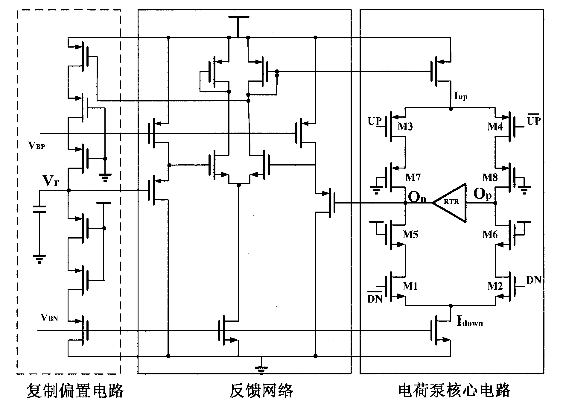
[0043] Figure 5 It is a schematic diagram of an embodiment of a self-tracking current type charge pump used in a phase-locked loop provided by the present invention. This embodiment is implemented using a CMOS process. The specific circuit description is as follows:

[0044] A self-tracking current-mode charge pump for a phase-locked loop, comprising:

[0045] A pull-up circuit, including a PMOS pull-up switch transistor, used to receive the control command signal output by the PFD; a PMOS current mirror, used to provide the charging current; a PMOS switch transistor, used to provide a discharge path when the pull-up switch transistor is turned off ;

[0046] a pull-down circuit including an NMOS pull-down switch tra...


PUM


Abstract

The invention discloses an automatic-tracking current type charge pump for a phase-locking loop, comprising an pull-up circuit, a pull-down circuit and a feedback control circuit, wherein the pull-up circuit comprises a P-channel metal oxide semiconductor (PMOS) pull-up switch transistor used for receiving control command signals output by a phase frequency detector (PFD), a PMOS current mirror used for supplying charge current, and a PMOS switch transistor used for supplying a discharge path when the pull-up switch transistor is shut off; the pull-down circuit comprises a N-channel metal oxide semiconductor (NMOS) pull-down switch transistor used for receiving control command signals output by the PFD, an NMOS current mirror used for supplying charge current, and an NMOS switch transistor used for supplying a charging path when the pull-down switch transistor is shut off; and the feedback control circuit comprises a PMOS transistor and an NMOS transistor and is used for dynamically controlling the magnitude of charge and discharge current. The automatic-tracking current type charge pump for the phase-locking loop realizes the dynamic tracking and matching of non-const current, the charge current and the discharge current, and has advantages of simple structure and easiness for realization.

Description

technical field [0001] The invention relates to the technical field of analog integrated circuit design, in particular to a self-tracking current type charge pump for a phase-locked loop, which can be applied to a charge pump phase-locked loop (Charge Pump Phase-Locking Loop CPPLL). Background technique [0002] The phase-locked loop (PLL) circuit was first proposed by H. de Bellescize in 1932, because of its excellent diversity, it has been widely used in the fields of electronics and communication. As an important application example, a phase-locked loop can be used to generate an output signal whose frequency is programmable, equal to a rational fractional multiple of a fixed input frequency. This kind of frequency synthesizer based on phase-locked loop is widely used in wireless terminal products. The diversity of the phase-locked loop also makes it applied to the digital system for the recovery of the clock signal and the generation of the clock signal. [0003] figu...

Claims


Application Information

Patent Timeline
Patent Type & Authority Applications(China)
IPC IPC(8): H02M3/07
Inventor 陈勇周玉梅陈铖颖
Owner 中科芯未来微电子科技成都有限公司
Why Eureka
Try Eureka