
Composite circuit board device and manufacturing method thereof

A circuit board and composite technology, applied in printed circuit components, structural connection of printed circuits, printed circuit assembly of electrical components, etc., can solve problems such as time-consuming assembly, save production costs, improve tension, and process procedures beautiful effect

Active Publication Date: 2012-06-27
AU OPTRONICS CORP
View PDF0 Cites 0 Cited by
  • Summary
  • Abstract
  • Description
  • Claims
  • Application Information

AI Technical Summary

Problems solved by technology

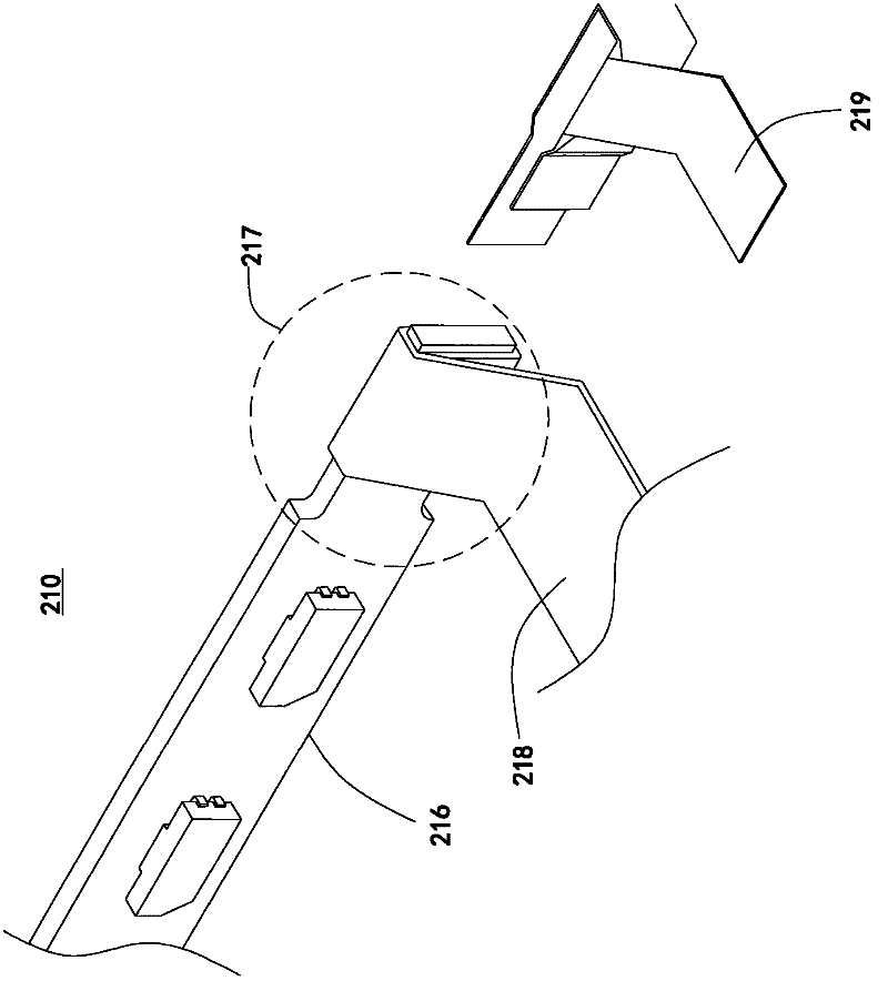
However, in the above-mentioned circuit board combination method, the bonding part 217 needs to be strengthened with the attachment component 219, which adds an attachment procedure to the process and consumes assembly time.

Method used


Image

  • Composite circuit board device and manufacturing method thereof
  • Composite circuit board device and manufacturing method thereof
  • Composite circuit board device and manufacturing method thereof

Examples


Embodiment Construction

[0063] The invention provides a composite circuit board device and a manufacturing method, which can effectively improve the tensile force of the circuit board by means of structural combination, and strengthen and fix the rigid printed circuit board assembly and the flexible printed circuit board. In addition, the traditional method of attaching components is eliminated, which improves product production efficiency and reduces the consumption of attached components. The composite circuit board device and manufacturing method of the present invention have the advantages of strengthening the tensile force of the circuit board and reducing product cost.

[0064] Such as Figure 3A In the illustrated embodiment, the composite circuit board device includes a rigid printed circuit board assembly 300 and a flexible printed circuit board 400. The rigid printed circuit board assembly 300 has a bearing section 310 and a connecting section 320 connected to each other. The carrying section...


PUM


Abstract

The invention discloses a composite circuit board device which comprises a hard printed circuit board assembly and a soft printed circuit board for providing a driving signal of a light source, wherein the hard printed circuit board assembly is provided with a bearing section and a connecting section, the light source is arranged on the bearing section, and the connecting section is electrically connected with the contact section of the soft printed circuit board, wherein a positioning hole is formed on the contact section of the soft printed circuit board, and a positioning piece is arrangedon the connecting section of the hard printed circuit board assembly. In addition, the soft printed circuit board is provided with at least two bent parts, and the soft printed circuit board is bent at the position of the contact section. By the special structural design of the combining part, the positioning piece of the hard printed circuit board assembly passes through the positioning hole of the soft printed circuit board to be combined and fixed, thus additional element processing programs are not needed, the product cost is lowered, and the manufacturing efficiency is improved.

Description

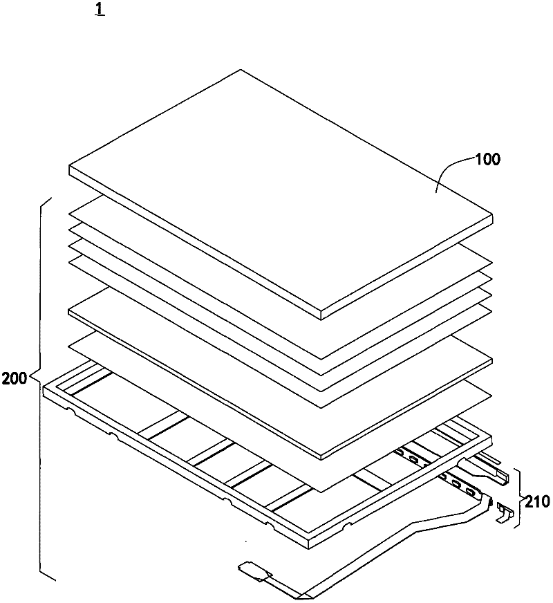
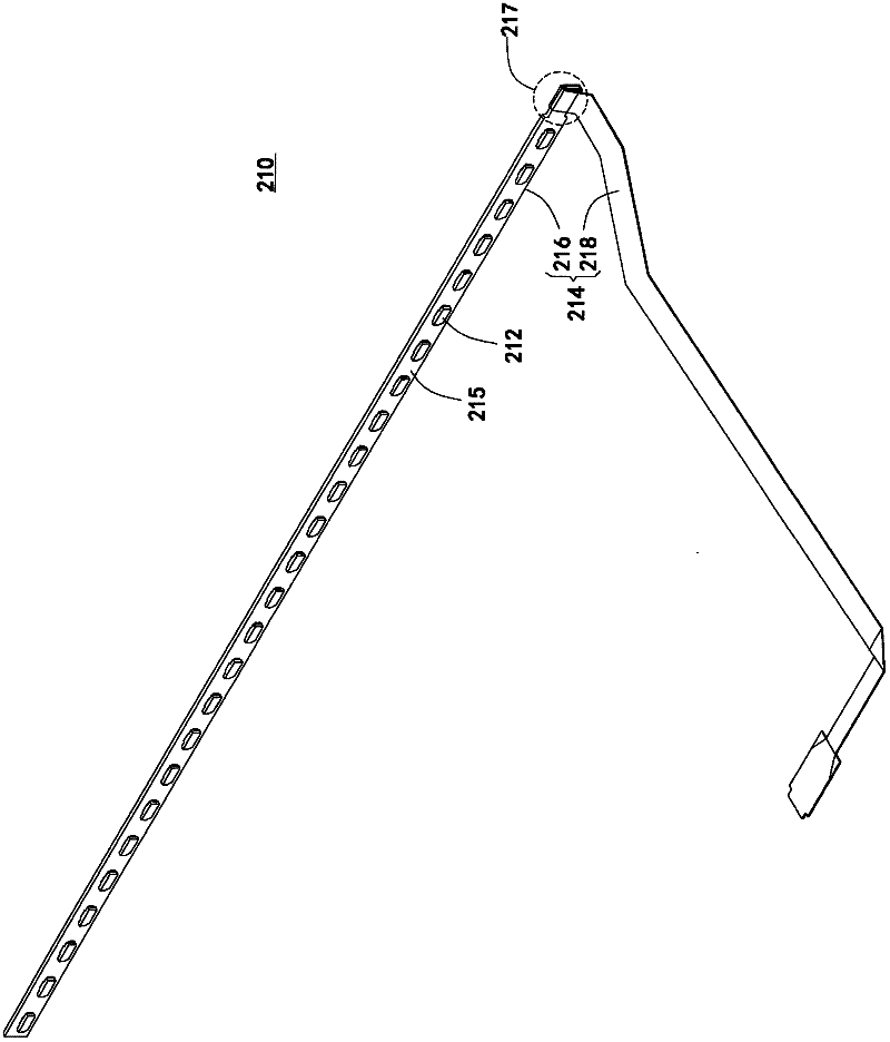
Technical field [0001] The present invention relates to a circuit board fixing device and method; in particular, by combining the positioning element structure corresponding to the circuit board and the fixing circuit board device, the use of adhesive materials is reduced. Background technique [0002] At present, the market is full of diversified display electronic products. Among them, liquid crystal display devices are extremely popular, including LCD TVs, desktop monitors, and notebook computer LCD screens. [0003] Such as figure 1 Shown is a schematic diagram of a conventional liquid crystal display device. The display device 1 has a display panel 100 and a backlight module 200. The backlight module 200 includes a light-emitting module 210. The light-emitting module 210 provides a backlight source required by the liquid crystal display panel 100, and the display device 1 can display a full-color image for the user to watch. [0004] See Figure 2A It is a schematic diagram of ...

Claims


Application Information

Patent Timeline
Patent Type & Authority Patents(China)
IPC IPC(8): H05K1/14H05K3/36
Inventor 陈清风蔡政旻王呈钰
Owner AU OPTRONICS CORP
Learn More