Apparatus for converting kinetic energy into usable power and improvement thereof

A technology of equipment and kinetic energy conversion, applied in mechanical equipment, mechanisms that generate mechanical power, electric components, etc., to achieve the effect of easy starting

Inactive Publication Date: 2011-04-06
POWER RAMPS
View PDF3 Cites 5 Cited by
  • Summary
  • Abstract
  • Description
  • Claims
  • Application Information

AI Technical Summary

Problems solved by technology

[0003] One problem with known electric motors is that when starting the electric moto...

Method used


Image

  • Apparatus for converting kinetic energy into usable power and improvement thereof
  • Apparatus for converting kinetic energy into usable power and improvement thereof
  • Apparatus for converting kinetic energy into usable power and improvement thereof

Examples


Embodiment Construction

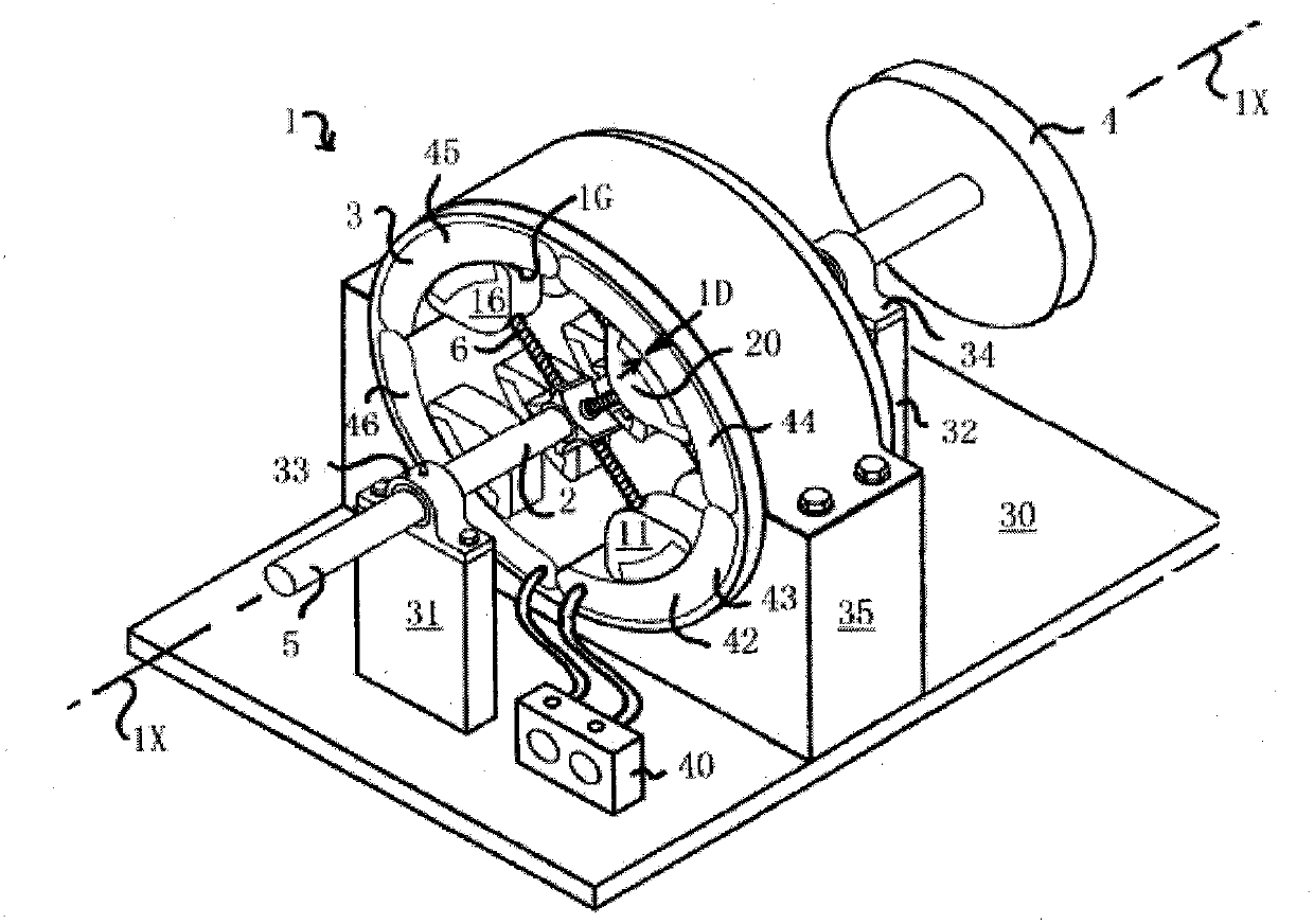
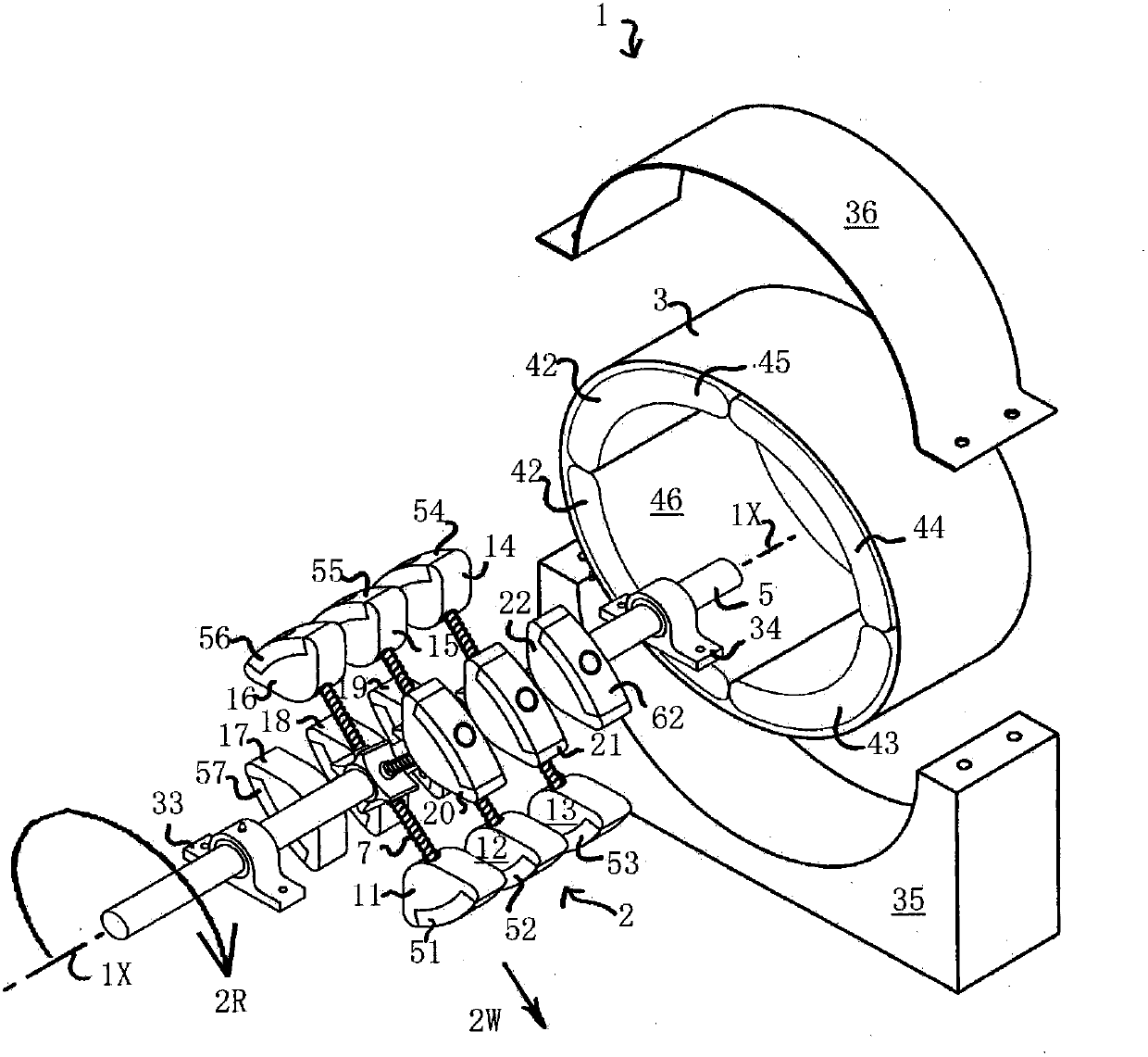
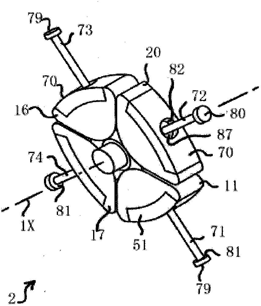
[0093] figure 1A rotating electrical machine 1 according to the invention is shown in , having a rotatable armature 2 and a stationary stator 3 . The armature 2 is arranged along the arrow 2R ( figure 2 The direction shown in ) is rotated around the axis 1X. The armature 2 has a plurality of movable parts 11 to 22 included, and these movable parts are figure 1 , figure 2 and Figure 4 shown in the second position, while the image 3 is shown in the first position. When the dimension 1D of the radial gap 1G between each movable part and the stator is small, each movable part can move from a first position when the armature is at rest to a second position when the armature is rotating (such as figure 1 and figure 2 shown in ). face from below Figure 5 , Figure 6 and Figure 7 In the description of , it can be seen that the gap decreases when the movable part moves from the first position to the second position. armature and stator such as Figure 17 Arranged as...


PUM


Abstract

Apparatus for converting kinetic energy into usable power (200), comprises a frame (204) arranged to be fixed in a vehicle running track (202) and a pluralityof plates (211 to 219 inclusive, and 221 to 229 inclusive) mounted to the frame. Each plate being movable in relation to the frame so as to drive an energy conversion means (232, 234). The energy conversion means has a rotating member (293 in Figure 19) having variable inertia.

Description

technical field [0001] The present invention relates to the conversion of kinetic energy from a moving vehicle. Background technique [0002] Electric rotating machines (such as generators and electric motors) used to convert kinetic energy into electrical energy generally have optimum operating speeds at which the electromagnetic interaction of moving parts with stationary devices produces desirable results. For the generators and motors described in this specification, the motion of the moving part is the rotation of the armature about the axis of the motor. For a generator, the desired result is an electrical output from a mechanical power input. For electric motors, the desired result is a mechanical power output from an electrical input. In such a rotating electric machine, the conversion of mechanical power to electric power or vice versa is achieved by the interaction between a magnetic field and a plurality of electric wires. The magnetic field can be derived from...

Claims


Application Information

Patent Timeline
IPC IPC(8): F03G7/08H02K7/12H02K21/00H02K7/18
CPCH02K7/06F03G7/08H02K7/1853
Inventor 彼得·内维尔·休斯安妮卡·玛丽安妮·休斯丽贝卡·安娜·休斯亚历山大·彼得·休斯
Owner POWER RAMPS
Why Eureka
Try Eureka