Heat exchanging ventilating apparatus

A ventilation device and heat exchange element technology, which is applied in household heating, heating methods, household heating, etc., can solve the problems of air not flowing through, unable to ventilate, and icing and blocking of air passages, so as to suppress condensation , high reliability, and the effect of reducing the diameter of the air path

Active Publication Date: 2011-04-06
MITSUBISHI ELECTRIC CORP
View PDF13 Cites 8 Cited by
  • Summary
  • Abstract
  • Description
  • Claims
  • Application Information

AI Technical Summary

Problems solved by technology

However, if the diameter of the air path in the heat exchange element is reduced, the air path is easily blocked by icing, and in the worst case, the air does not flow through the heat exchange element and cannot be ventilated

Method used


Image

  • Heat exchanging ventilating apparatus
  • Heat exchanging ventilating apparatus
  • Heat exchanging ventilating apparatus

Examples


Embodiment approach 1

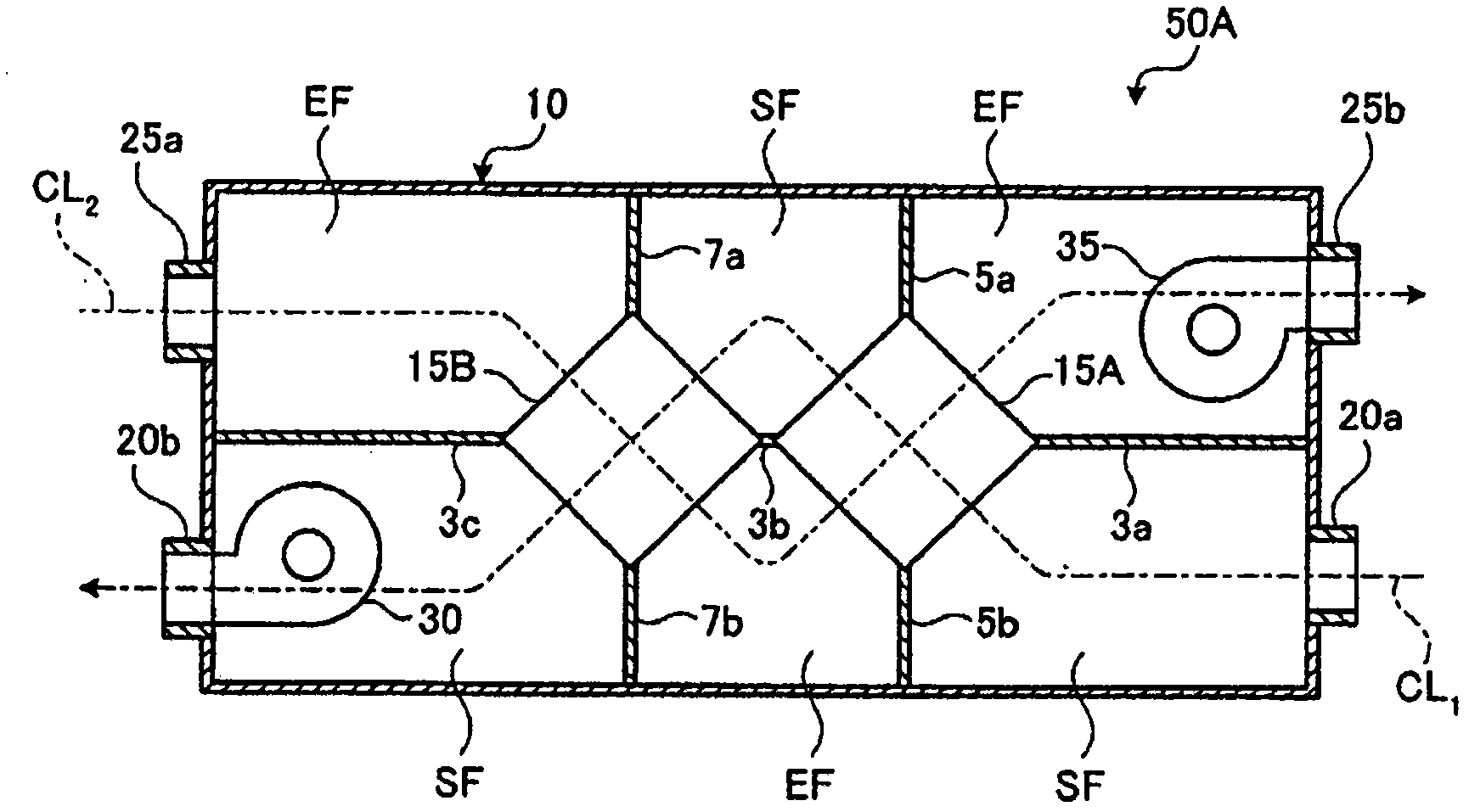
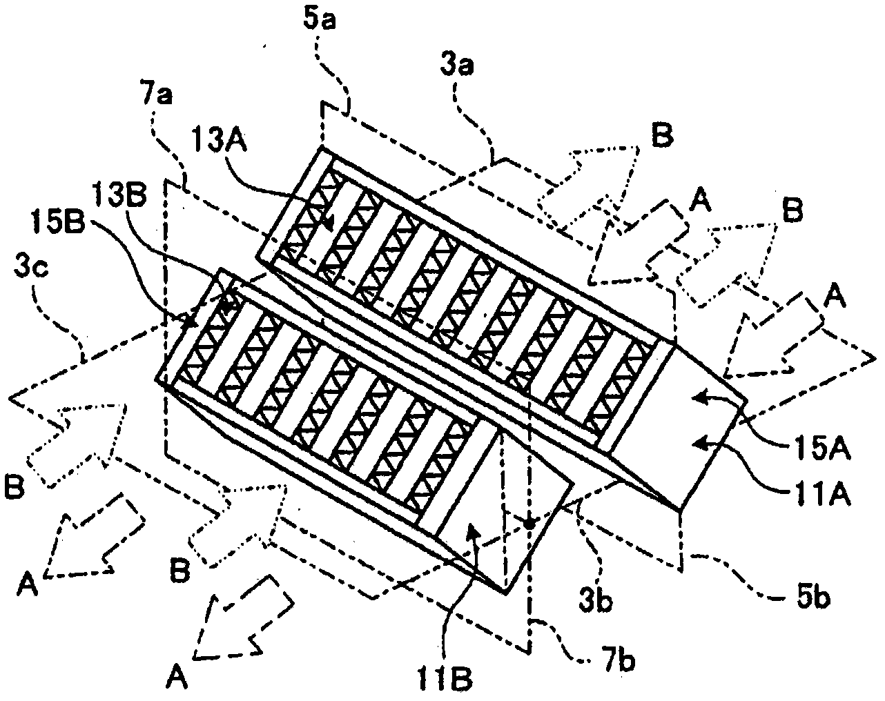
[0043] figure 1 It is a longitudinal sectional view schematically showing an example of the heat exchange ventilator of the present invention. figure 2 is roughly figure 1 The perspective view of the two heat exchange components used in the shown heat exchange ventilator. figure 2 The components shown in the figure 1 If the constituent parts shown are the same, mark with figure 1 The tags in the same tag.

[0044] figure 1 The shown heat exchange and ventilation device 50A has: a frame body 10, two heat exchange assemblies 15A, 15B arranged in the central part of the frame body 10, an outside air suction port 20a installed on the frame body 10, and an outside air blower. Outlet 20b, room air suction port 25a and room air blowing port 25b, air supply fan 30 arranged in frame 10, exhaust fan 35 arranged in frame 10, control function of air supply fan 30 and exhaust fan 35 Action control unit (not shown).

[0045] Three horizontal partition walls 3a, 3b, and 3c and four ...

Embodiment approach 2

[0062] The heat exchange efficiency of the heat exchange element can be adjusted by changing the volume and heat transfer area of ​​the heat exchange element. In addition, the latent heat exchange efficiency can also be adjusted according to the material of the heat exchange element, the amount and type of the moisture absorbent contained. In the heat exchange and ventilation device of the present invention, the heat exchange efficiency of each heat exchange element can be adjusted by adjusting the volume and heat transfer area of ​​the heat exchange element, or the amount and type of moisture absorbent contained in the heat exchange element.

[0063] Figure 4 It is a longitudinal sectional view schematically showing an example of a heat exchange ventilator that adjusts the heat exchange efficiency of each heat exchange element by changing the respective volumes and heat transfer areas of a plurality of heat exchange elements. exist Figure 4 Of the constituent parts shown,...

Embodiment 1

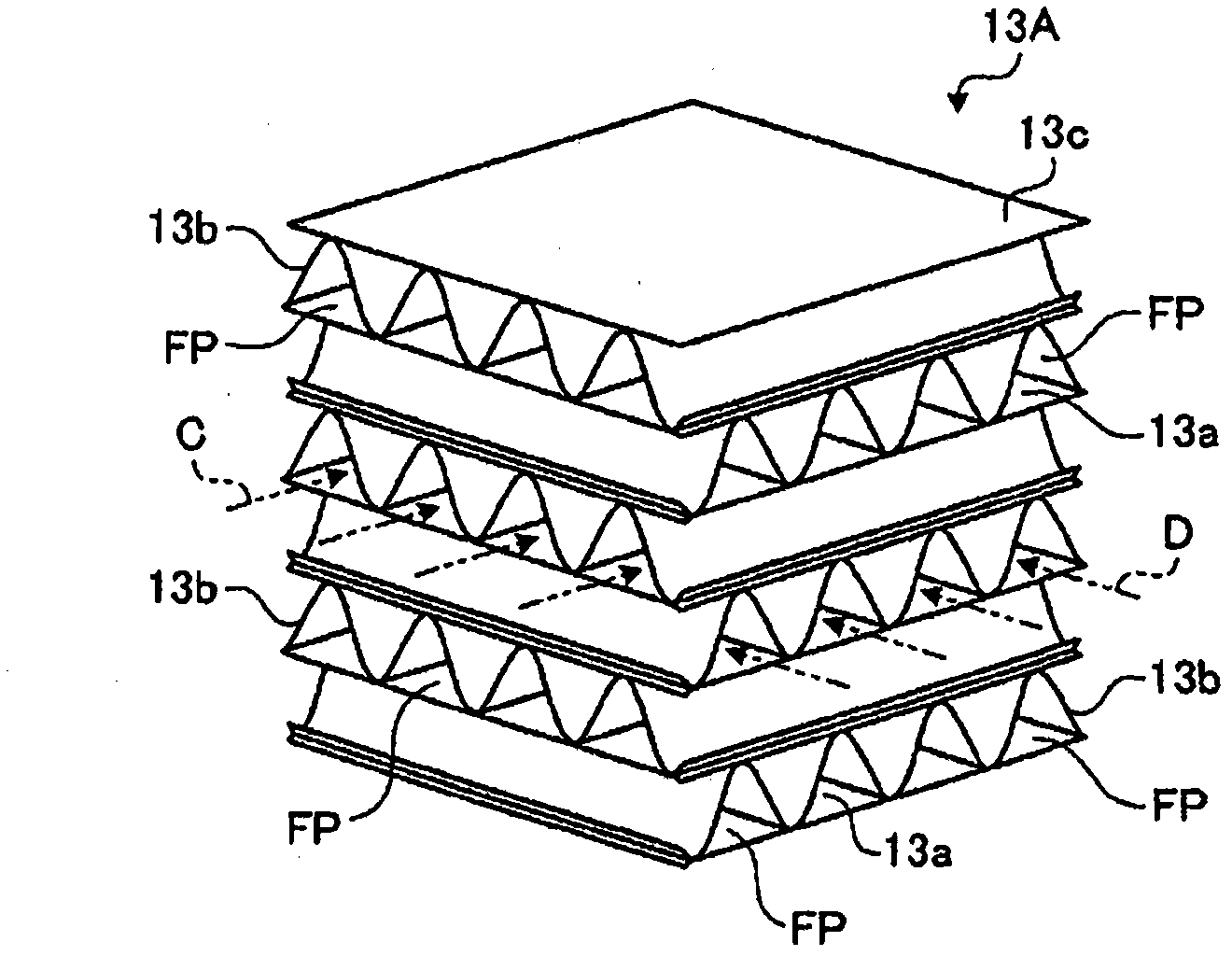
[0074] As the heat exchange element arranged on the outdoor side and the heat exchange element arranged on the outdoor side, a Figure 3-1 The cross-flow total heat exchange element of the same structure as the shown heat exchange element 13A is obtained with figure 1 The heat exchange ventilator 50A shown is a similarly constructed heat exchange ventilator.

[0075] At this time, the partition member in the total heat exchange element disposed on the outdoor side is made of a composite moisture-permeable membrane. This composite moisture-permeable membrane is formed as follows. On the surface of a porous sheet made of polytetrafluoroethylene with a thickness of 25 μm, a polyurethane resin containing an oxyethylene group is thinly coated to become non-porous and highly hydrophilic. The molecular film is point-bonded with a breathable nonwoven fabric on the back of the hydrophilic polymer film. The spacer is made of a sheet with a thickness of about 100 μm made by mixing wood...


PUM


Abstract

A heat exchanging ventilating apparatus comprises an air supply channel which takes in the outside air and blows it out indoors, an air exhaust channel which takes in the indoor air and blows it out outdoors, and a plurality of heat exchanging elements for exchanging heat between the outside air which flows down in the air supply channel and the indoor air which flows down the exhaust air channel. The plurality of heat exchanging elements are arranged in series from the outdoor side toward the indoor side. In configuring the heat exchanging ventilating apparatus, the sensible heat exchanging efficiency of the heat exchanging element located on the most outdoor side is set higher than that of the heat exchanging element located on the indoor side adjacently to the heat exchanging element located on the most outdoor side or the latent heat exchanging efficiency of the heat exchanging element located on the most outdoor side is set lower than that of the heat exchanging element located on the indoor side adjacently to the heat exchanging element located on the most outdoor side to prevent bedewing and freezing of the heat exchanging element on the outdoor side.

Description

technical field [0001] The present invention relates to a heat exchange ventilator that ventilates while exchanging sensible heat or latent heat between two air streams with different temperatures or humidity. Background technique [0002] Especially in summer and winter, due to the large temperature difference between indoors and outdoors, when using refrigeration equipment or heating equipment that has undergone a refrigeration cycle for indoor ventilation, if the outside air is directly introduced into the room, the load on the refrigeration equipment or heating equipment will increase. increase. The so-called ventilation load increases. [0003] For this reason, a heat exchange and ventilation device has been developed, which uses heat exchange elements to exchange heat between the outside air taken in from the outside and the indoor air discharged from the room during ventilation. In this heat exchange ventilator, it is required to perform heat exchange while securing...

Claims


Application Information

Patent Timeline
Patent Type & Authority Applications(China)
IPC IPC(8): F24F7/08
CPCF24F12/006Y02B30/563Y02B30/16F24F2012/007F24F13/30Y02B30/56
Inventor 高田胜大西茂树荒井秀元
Owner MITSUBISHI ELECTRIC CORP
Why Eureka
Try Eureka