
Pneumatic conveying method for powder materials

A technology for pneumatic conveying and materials, applied in the direction of conveyors, conveying bulk materials, transportation and packaging, etc., can solve the problem that the pneumatic ash removal system is difficult to meet the economic, practical, reliable, energy-saving, and the down-drawing warehouse pump is difficult to control the discharge speed , Conveying compressed air and conveying low efficiency of dry ash, to achieve the effect of saving equipment and materials, saving warehouse pumps and valves, and facilitating the speed of ash discharge

Active Publication Date: 2011-04-13
ZHENJIANG CITY POWER STATION AUXILIARY MACHINERY PLANT
View PDF5 Cites 29 Cited by
  • Summary
  • Abstract
  • Description
  • Claims
  • Application Information

AI Technical Summary

Problems solved by technology

[0002] The ash and slag discharged from the boilers of coal-fired power plants have been developed and utilized as a resource. Therefore, the dry ash of the boiler flue gas dust collector generally adopts the pneumatic ash removal method. Pneumatic ash removal system is difficult to meet the requirements of economy, practicality, reliability and energy saving. The main problems are as follows:
It is the main reason for the large number of warehouse pumps and low conveying efficiency of the existing pneumatic ash removal system
[0005]3. The conveying method of all warehouse pumps is to convey the compressed air in the chamber pump mixed with the dry ash and then convey intermittently. It is necessary to transport the dry ash of the first set of chamber pumps The dry ash in the second set of warehouse pumps can only be transported after arriving at the ash warehouse, forming a common law that the conveying distance is inversely proportional to the conveying ash-gas ratio, which is the main reason for the low efficiency of conveying compressed air to convey dry ash
[0007]5. Since it is difficult to control the discharge speed of the existing down-drawing silo pump, it is easy to cause pipe blockage

Method used


Image

  • Pneumatic conveying method for powder materials
  • Pneumatic conveying method for powder materials
  • Pneumatic conveying method for powder materials

Examples


Embodiment Construction

[0019] The powder material delivery method provided by the invention will be further described in detail below in conjunction with the accompanying drawings:

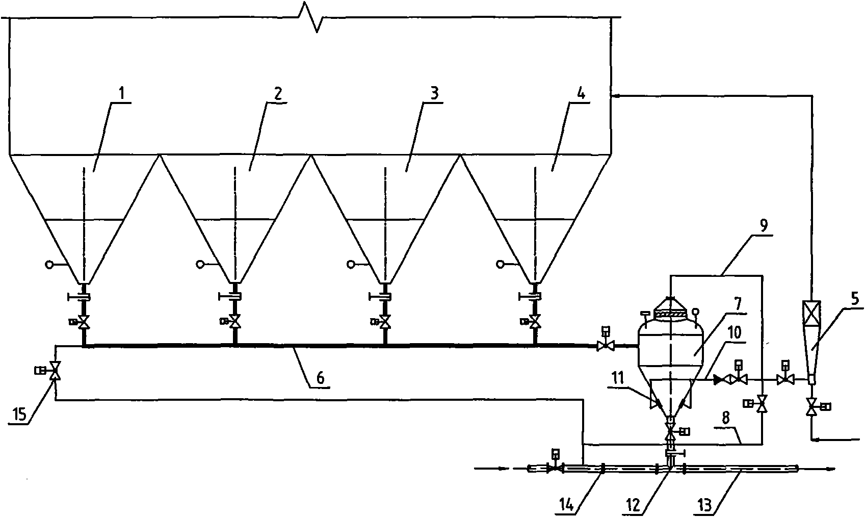
[0020] Such as figure 1 As shown, the warehouse pump produces negative pressure device 5 to generate negative pressure in the warehouse pump 7, and the end section of the negative pressure ash conveying pipeline 6 away from the warehouse pump is provided with a positive pressure air supply device 15, and the positive pressure air supply device 15 is opened to dry air. The ash forms a thrust, and under the joint action of negative pressure suction, positive pressure thrust, and dry ash self-weight, the dry ash in the ash hoppers 1, 2, 3, and 4 enters the warehouse pump 7 through the negative pressure conveying pipeline 6, and the negative pressure ash loading is completed;

[0021] The compressed air pressurizes the warehouse pump through the pressurized fluidization pipeline 8 through the pressurization pipeline 9, and ...

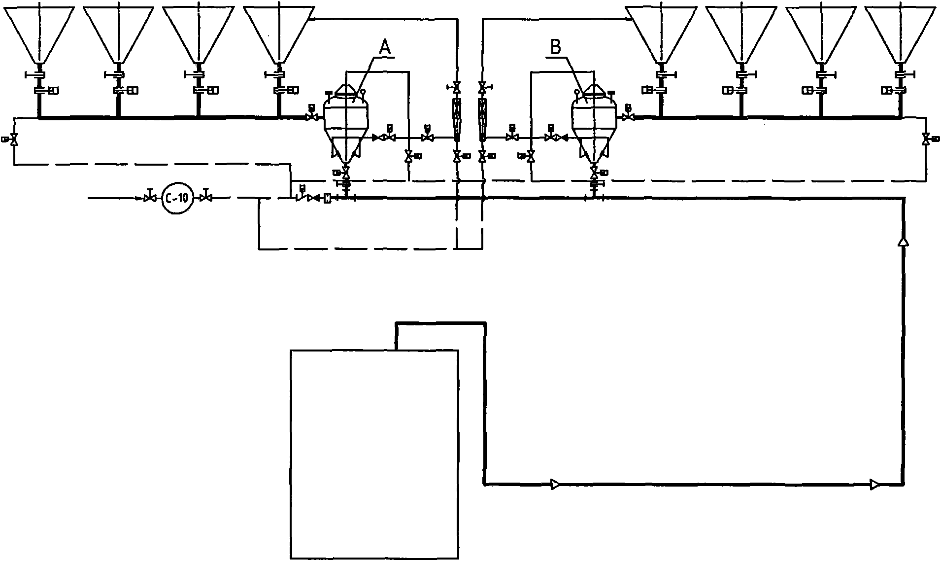
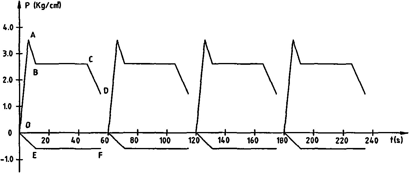

PUM


Abstract

The invention relates to a pneumatic conveying method for powder materials, in particular to a pneumatic conveying method for pneumatic ash handling for large and medium-sized coal-fired power plants and limestone powder of a flue gas desulfurization system of a boiler. The pneumatic conveying method comprises two steps of negative-pressure ash loading and positive-pressure conveying and is economic and practical. One set of multi-function warehouse pump can be used for conveying ashes in a plurality of ash buckets, and therefore a lot of equipment and materials are saved. The multi-function warehouse pump can complete negative-pressure feeding and positive-pressure conveying, so that the integral structure is simplified, and reliability is enhanced. Meanwhile, the ashes are conveyed to a final ash silo once, a middle ash silo is saved, and a lot of warehouse pumps and valves are also saved. As a positive-pressure conveying pipeline is provided with a flow adjusting device and is separated from a fluidization pressurization pipeline, the ash handling speed is conveniently controlled, the conveying efficiency is increased and the pipe blocking probability is reduced.

Description

technical field [0001] The invention relates to a method for pneumatically conveying powder materials, in particular to a method for pneumatically conveying limestone powder in a large and medium-sized coal-fired power plant and a boiler flue gas desulfurization system. Background technique [0002] The ash and slag discharged from the boilers of coal-fired power plants have been developed and utilized as a resource. Therefore, the dry ash of the boiler flue gas dust collector generally adopts the pneumatic ash removal method. Pneumatic ash removal system is difficult to meet the requirements of economy, practicality, reliability and energy saving. The main problems are as follows: [0003] 1. The domestic coal-fired power plants have larger and larger single-unit capacity (such as a single-unit capacity of 1000MW), the increase in the number of ash hoppers for boiler flue gas dust collectors, the increase in ash volume, and the long transportation distance. It is very diffi...

Claims


Application Information

Patent Timeline
IPC IPC(8): B65G53/16B65G53/34B65G53/50B65G53/58
Inventor 虞瑞鹤崔功龙张凯
Owner ZHENJIANG CITY POWER STATION AUXILIARY MACHINERY PLANT
Learn More