Ventilation and forced air cooling device in LED (light emitting diode) bulb

A technology of LED light bulbs and heat sinks, which is applied in the electronic field and can solve the problems of insufficient heat dissipation of the light source, inability to meet the use of LED lamps, and failure of light bulbs to dissipate heat.

Active Publication Date: 2011-04-13
LEEDARSON IOT TECH INC
View PDF4 Cites 7 Cited by
  • Summary
  • Abstract
  • Description
  • Claims
  • Application Information

AI Technical Summary

Problems solved by technology

The disadvantage of the heat dissipation device of this structure LED lamp is that its heat dissipation is generally realized by the heat sink installed on the lamp housing or inside, and only the heat dissipation of the lamp housing part can be realized. Since the heat generation of the LED light source is 360 degrees, the front of the light source The heat is mainly concentrated in the bubble
Therefore, the heat dissipation of the bulb, especially the light source part, is actually not sufficient, and the bulb cannot achieve complete heat dissipation.
Since the outer bulb of the high-power and large-angle LED bulb is larger than a hemispherical structure, the volume that can be used for the radiator is greatly reduced, and it cannot meet the use of LED lamps with high-power and large-angle lighting.

Method used


Image

  • Ventilation and forced air cooling device in LED (light emitting diode) bulb
  • Ventilation and forced air cooling device in LED (light emitting diode) bulb
  • Ventilation and forced air cooling device in LED (light emitting diode) bulb

Examples


Embodiment Construction

[0031] Below in conjunction with accompanying drawing and embodiment the present invention is described in detail:

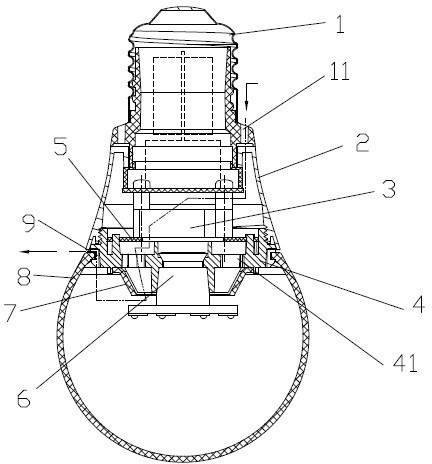
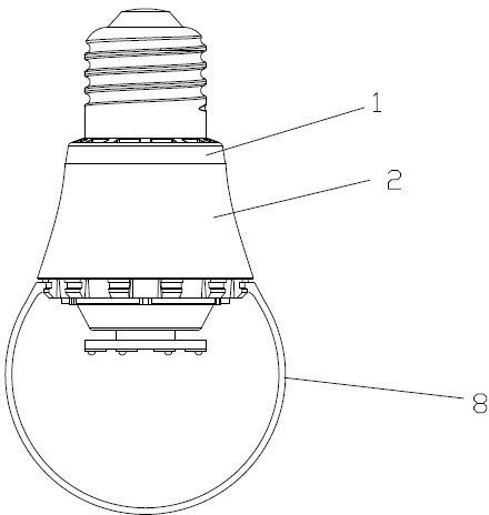
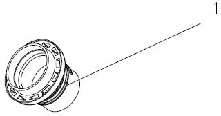
[0032] Such as figure 1 - Figure 13 The illustrated embodiment of the present invention, the forced ventilation cooling device inside the LED bulb, includes: Lamp base insulator 1: there is a vent 11 on it; lamp housing 2: clamped on the lamp base; micro fan 3: installed on the lamp Inside the shell; two-way radiator 4: set between the lamp shell and the lampshade, one end is clamped on the lamp body, the other end is matched with the lampshade, and the two-way radiator is provided with a through hole 41 to connect the lamp shell and the inner cavity of the lampshade; the current limiting plate 5: set in the lamp housing, covered above the two-way heat sink; heat conduction column 6: one end is clamped on the two-way heat sink, and the other end cooperates with the LED light-emitting element assembly; wind guide reflector 7: set in the lampshade, and the two...


PUM


Abstract

The invention discloses a ventilation and forced air cooling device in an LED bulb (light emitting diode). The device disclosed by the invention comprises a bulb-holder insulator, a lamp housing, a mini-fan, a bidirectional radiator, a current-limiting board, a heat-conducting pillar, a wind-conducting reflector and a lampshade, wherein the bulb-holder insulator is provided with an air vent; the lamp housing is clamped at a bulb holder; the mini-fan is arranged in the lamp housing; the bidirectional radiator is arranged between the lamp housing and the lampshade, one end of the bidirectional radiator is clamped at the lamp housing, the other end of the bidirectional radiator is matched with the lampshade, and the bidirectional radiator is provided with a through hole communicated with cavities of the lamp housing and the lampshade; the current-limiting board is arranged in the lamp housing, and is covered on the upper part of the bidirectional radiator; one end of the heat-conducting pillar is clamped at the bidirectional radiator, and the other end of the heat-conducting pillar is matched with LED light emitting components; the wind-conducting reflector is arranged in the lampshade and matched with the bidirectional radiator; and the lampshade is matched with the bidirectional radiator for positioning, and an air vent formed at the matched position of the bidirectional radiator and the lampshade is communicated with the air vent at the bulb holder so as to form an airflow channel. The device provided by the invention has the advantages that for reaching a heat-exchange control temperature, the cooling device in the LED bulb can carry out forced-air cooling on cooling fins in the bulb and cooling fins in the radiator and then discharge hot air from the airflow channel so as to meet the temperature requirement for heat exchange.

Description

technical field [0001] The invention belongs to the field of electronic technology, and relates to a heat dissipation device for an LED lamp, in particular to a heat dissipation device for realizing ventilation and forced air supply in a bubble. Background technique [0002] The existing LED lamps generally include a lamp base, a lamp body and a lampshade. An LED light-emitting unit is arranged inside the lampshade, and a heat dissipation device is arranged on or inside the lampshade. The disadvantage of the heat dissipation device of this structure LED lamp is that its heat dissipation is generally realized by the heat sink installed on the lamp housing or inside, and only the heat dissipation of the lamp housing part can be realized. Since the heat generation of the LED light source is 360 degrees, the front of the light source The heat is mainly concentrated in the bubble. Therefore, the heat dissipation of the bulb, especially the light source part, is actually not suf...

Claims


Application Information

Patent Timeline
Patent Type & Authority Applications(China)
IPC IPC(8): F21V29/02F21Y101/02F21V29/67F21V29/71
Inventor 王辉炎
Owner LEEDARSON IOT TECH INC
Why Eureka
Try Eureka