Drying and humidifying integrated machine

An all-in-one drying technology, applied in heating methods, lighting and heating equipment, applications, etc., can solve the problems of shortened machine life, high power consumption, and small dehumidification, and achieve resource and space saving, convenient movement, and strong The effect of practicality

Inactive Publication Date: 2011-04-13
DALIAN UNIV
View PDF5 Cites 26 Cited by
  • Summary
  • Abstract
  • Description
  • Claims
  • Application Information

AI Technical Summary

Problems solved by technology

[0004] Most of the products currently on the market are either humidifiers that mainly increase air humidity or dehumidifiers that mainly dry, and there is no product that combines the two
In addition, dehumidification of air conditioners is gradually becoming the mainstream of the market, but the main function of air conditioners is cooling and heating. Air conditioners with independent dehumidification function can dehumidify, but the dehumidification capacity is small and dehumidification is slow; They are all low, and most of the time it is below 20°C. At this time, the air conditioner blows out cold air for dehumidification. The more dehumidified, the colder it is, which makes people feel quite uncomfortable.
In addition, since the air conditioner is fixed, it can only dehumidify in a small local area, and it is not suitable to install air conditioners in places with high humidity such as bathrooms and kitchens.
More importantly, when the air conditioner is dehumidified, the load operation is increased several times, which not only consumes a lot of power, but also damages the compressor and shortens the life of the machine.

Method used


Image

  • Drying and humidifying integrated machine
  • Drying and humidifying integrated machine

Examples


Embodiment Construction

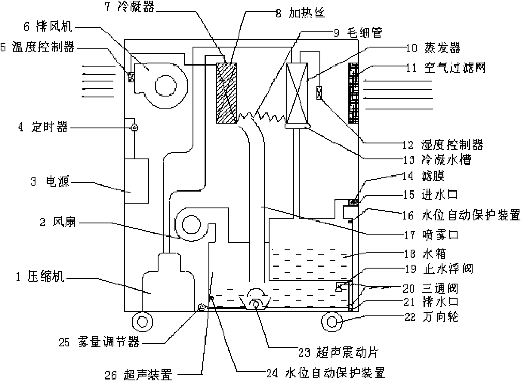
[0016] Such as figure 1 The drying and humidifying integrated machine shown is mainly composed of a compressor 1, a fan 2, a power supply 3, a timer 4, a temperature controller 5, an exhaust fan 6, a condenser 7, a heating wire 8, a capillary tube 9, an evaporator 10, Air filter 11, humidity controller 12, condensation water tank 13, filter membrane 14, water inlet 15, automatic water level protection device 16, spray port 17, water tank 18, water stop float valve 19, three-way valve 20, drain port 21, Universal wheel 22, ultrasonic vibrating sheet 23, automatic water level protection device 24, fog volume regulator 25, ultrasonic device 26, compressor 1, fan 2, exhaust fan 6, heating wire 8, ultrasonic vibrating sheet 23 powered by power supply 3 One end of the compressor 1 is connected to the evaporator 10, and the other end is connected to the condenser 7, and the evaporator 10 and the condenser 7 pass through the capillary tube 9 to form a circulation loop. The compressor...


PUM


Abstract

The invention discloses a drying and humidifying integrated machine. One end of a compressor is connected with an evaporator, the other end of the compressor is connected with a condenser, and a circulation loop is formed between the evaporator and the condenser through a capillary tube; the steam in the air is condensed into water by the evaporator to flow into a condensation water trough, then the water is injected into an ultrasonic device through a water tank, the water is atomized by an ultrasonic vibration sheet, the atomized water is discharged into the air from a fog nozzle, and the vibration frequency of the ultrasonic vibration sheet is controlled by a fog quantity regulator, thereby regulating the humidifying quantity; a fan 2 is used for dissipating the heat in the ultrasonic device and enabling the ultrasonic atomized water to be spouted from the fog nozzle; a timer is used for determining the working time of the compressor and the ultrasonic vibration sheet; four universal wheels by which an instrument can be moved conveniently are installed on the machine body; and a humidity controller, an air filtering screen, a heating wire, an exhaust fan, a temperature controller, a water level automatic protector, a filtering membrane and other accessories are also installed on the machine body. The machine disclosed by the invention can be used for realizing multiple purposes, has strong practicability, can realize automatic regulation according to the indoor temperature to create an optimal humid temperature environment, is energy-saving and environment-friendly, andcan be moved conveniently.

Description

technical field [0001] The invention patent belongs to the technical field of environmental protection. In particular, it relates to a humidity regulating device with small volume, strong applicability, energy saving and environmental protection. Background technique [0002] Humidity is an important factor affecting the quality of the air environment, and the relative humidity in the air will have a corresponding impact on the people and objects in the environment. Studies have found that humidity is the main factor that constitutes air cleanliness and comfort, thereby affecting product quality and people's quality of life. [0003] With the improvement of people's living standards, the requirements for the environment are more stringent. In winter, the climate is relatively dry, and the dust and suspended particles in the room are seriously polluted, and germs are easy to spread rapidly. In this environment, people are prone to colds, skin allergies, and body immunity de...

Claims


Application Information

Patent Timeline
Patent Type & Authority Applications(China)
IPC IPC(8): F24F1/02F24F11/02
Inventor 邱琳刘娜娜苑艳霞裴青王惠国冯宝民
Owner DALIAN UNIV
Why Eureka
Try Eureka