In situ measurement method for relative dielectric constant of stratum

A technology of relative permittivity and formation, applied in electromagnetic field characteristics, measurement devices, measurement of electrical variables, etc., can solve the problems of inability to represent formation medium and influence, and achieve the effect of improving accuracy and detection accuracy

Inactive Publication Date: 2011-04-13
POWERCHINA HUADONG ENG COPORATION LTD +2
View PDF3 Cites 14 Cited by
  • Summary
  • Abstract
  • Description
  • Claims
  • Application Information

AI Technical Summary

Problems solved by technology

Due to the effects of air-drying, dehydration, stress relaxation, etc. during the production and preservation of the specimen, the water content and properties of the rock sample have undergone major changes, which are quite different from th

Method used


Image

  • In situ measurement method for relative dielectric constant of stratum
  • In situ measurement method for relative dielectric constant of stratum
  • In situ measurement method for relative dielectric constant of stratum

Examples


Embodiment 1

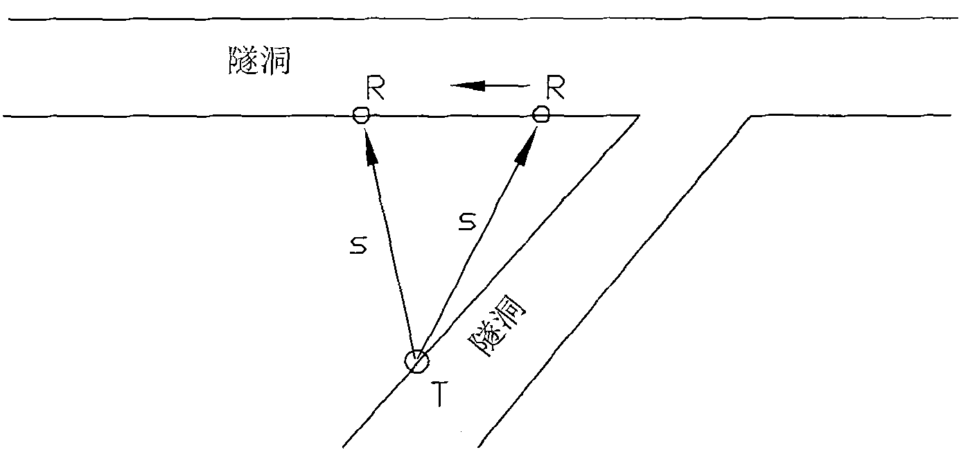
[0029] Such as figure 1 As shown, the present embodiment has two intersecting tunnels, and the relative permittivity of the formation is obtained by using the direct wave method to measure the propagation velocity of the formation electromagnetic wave on the spot. The steps are as follows:

[0030] 1) Place the transmitting antenna T and receiving antenna R of the geological radar in two intersecting tunnels, and fix the transmitting antenna, move the receiving antenna to change the straight-line distance s between the two antennas, and measure the electromagnetic waves at different distances from the transmitting antenna The travel time t to the receiving antenna is used to calculate the electromagnetic wave propagation velocity v in the formation:

[0031] v = s t

[0032] In the formula, s is the distance from the transmitting antenna to the receiving antenna, t is the travel time of the electromagnetic wave, and v i...

Embodiment 2

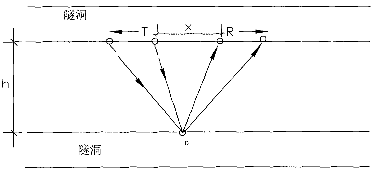
[0037] Such as figure 2 As shown, the present embodiment has two substantially parallel tunnels, and the relative permittivity of the formation is obtained by using the wide-angle reflection method to measure the propagation velocity of the formation electromagnetic wave on the spot. The steps are as follows:

[0038] 1) Place the transmitting antenna T and receiving antenna R of the geological radar on the side wall of one of the tunnels, move the transmitting antenna and receiving antenna in opposite directions, adjust the distance x between the two antennas from near to far, and measure the reflection of known reflection interfaces with different distances Electromagnetic wave travel time t. Such as figure 2 As shown, the electromagnetic wave reaches the receiving antenna R after being reflected by the common reflection point O from the transmitting antenna T, Therefore, the formation electromagnetic wave velocity v can be obtained:

[0039] v = ...

Embodiment 3

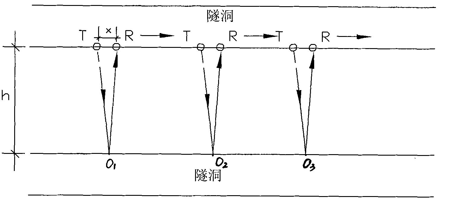
[0045] Such as image 3 As shown, the present embodiment has two substantially parallel tunnels, and the relative permittivity of the formation is obtained by using the narrow-angle reflection method to measure the propagation velocity of the electromagnetic wave in the formation on the spot. The steps are as follows:

[0046] 1) Place the transmitting antenna T and receiving antenna R of the geological radar on the side wall of one of the tunnels, and keep a relatively fixed distance x, move the transmitting antenna and receiving antenna synchronously, and measure the reflected electromagnetic wave travel time t of the known reflection interface. Such as image 3 As shown, the electromagnetic wave passes from the transmitting antenna T through the reflection point (O 1 , O 2 or O 3 ) reaches the receiving antenna R after reflection, Then get the formation electromagnetic wave velocity v:

[0047] v = 2 × ...


PUM


Abstract

The invention relates to an in situ measurement method for a relative dielectric constant of a stratum. The method solves the technical problem of avoiding an error or a mistake caused by using a stratum rock sample measurement parameter or an estimated numerical value by directly measuring electromagnetic wave speed and relative dielectric constant of the in situ stratum on site and directly using the actually measured electromagnetic wave speed and relative dielectric constant for time depth conversion and image analysis of radar detection. In order to solve the problem, the invention adopts the technical scheme that the method comprises the following steps of: measuring the propagation speed of electromagnetic wave of the stratum on site by adopting a direct wave method, a wide angle reflection method or a narrow angle reflection method; and reckoning the relative dielectric constant of the stratum according to a formula epsilon r=c2/v2. The method can be used for geological advanced forecast and geological radar detection of tunnels or holes.

Description

technical field [0001] The invention relates to an on-site measurement method for the relative dielectric constant of formations. It is suitable for geological advance prediction and geological radar detection of tunnels or tunnels. Background technique [0002] Formation dielectric constant is an important parameter for geological radar prediction or geological radar detection. Usually, stratum rock samples are selected, and the relative dielectric constant of rock and soil specimens is measured in the laboratory by methods such as reflection method, transmission method, coherent method and standing wave method. constant. Due to the effects of air-drying, dehydration and stress relaxation during the production and preservation of the specimen, the water content and properties of the rock sample have changed greatly, which is quite different from the properties of the in-situ formation. The relative permittivity of rock samples can no longer represent the formation medium,...

Claims


Application Information

Patent Timeline
IPC IPC(8): G01R27/26G01R29/08
Inventor 单治钢蔡连初黄世强周春宏
Owner POWERCHINA HUADONG ENG COPORATION LTD
Why Eureka
Try Eureka