
Phase unwrapping method based on shearing principle

A technology of unpacking and phasing, applied in the direction of instruments, etc., can solve the problems of undersampling, wrapping phase fringe breakage, limiting the spatial bandwidth product of photoelectric conversion devices, etc., to reduce the difficulty and reduce the occurrence of undersampling.

Inactive Publication Date: 2011-04-13
KUNMING UNIV OF SCI & TECH
View PDF1 Cites 6 Cited by
  • Summary
  • Abstract
  • Description
  • Claims
  • Application Information

AI Technical Summary

Problems solved by technology

In practical applications, since the resolution of traditional recording media has reached 4000-10000 lines / mm, the resolution of CCD and CMOS is still 100-200 lines / mm, and the effective photosensitive surface size of CCD and CMOS is still The centimeter level (although it can be expanded by the method of synthetic aperture, but it is technically inconvenient), limits the space-bandwidth product of the photoelectric conversion device. Therefore, the spatial frequency of the digital holographic reproduction light field phase is generally high, and wrapped phase fringes often appear Fracture and undersampling lead to a large number of unreliable data points in the wrapped phase, which brings great difficulties to the phase unwrapping algorithm, especially when the phase changes rapidly in space and a large number of undersampling occurs. The package can't even complete smoothly

Method used


Image

  • Phase unwrapping method based on shearing principle
  • Phase unwrapping method based on shearing principle
  • Phase unwrapping method based on shearing principle

Examples


Embodiment Construction

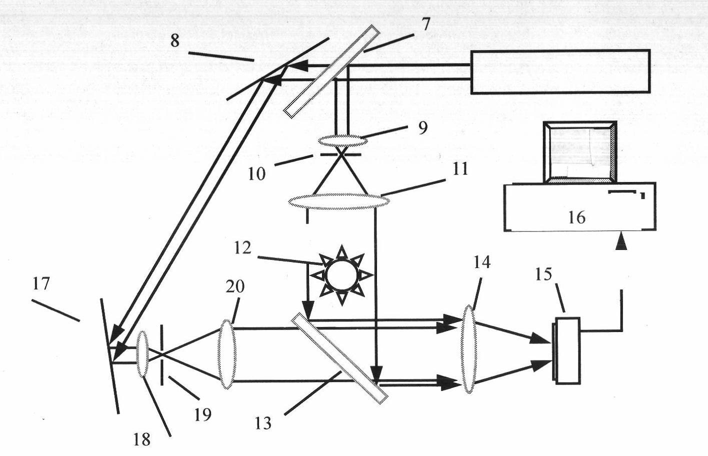
[0021] first use as figure 2 The recording optical path of the digital hologram shown records a digital hologram. The laser beam emitted by the laser 6 is divided into two beams by the beam splitter 7, one of which is converged by the microscopic objective lens 9 and passes through the pinhole filter 10, then becomes parallel light by the collimator lens 11, and irradiates the object to be measured 12 On the top, the transmitted light passes through the beam splitter 13 as the object light and converges on the CMOS 15 through the converging lens 14; the other beam is converged by the total reflection mirror 8, 17 and the microscope objective lens 18 and passes through the pinhole filter 19, and then irradiates to the splitter. On the beam mirror 13, the reference light reaches the CMOS 15 through the converging lens 14. The reference and object light interfere on the CMOS 15, and the light intensity is converted into an electrical signal, which is transmitted to the computer...


PUM


Abstract

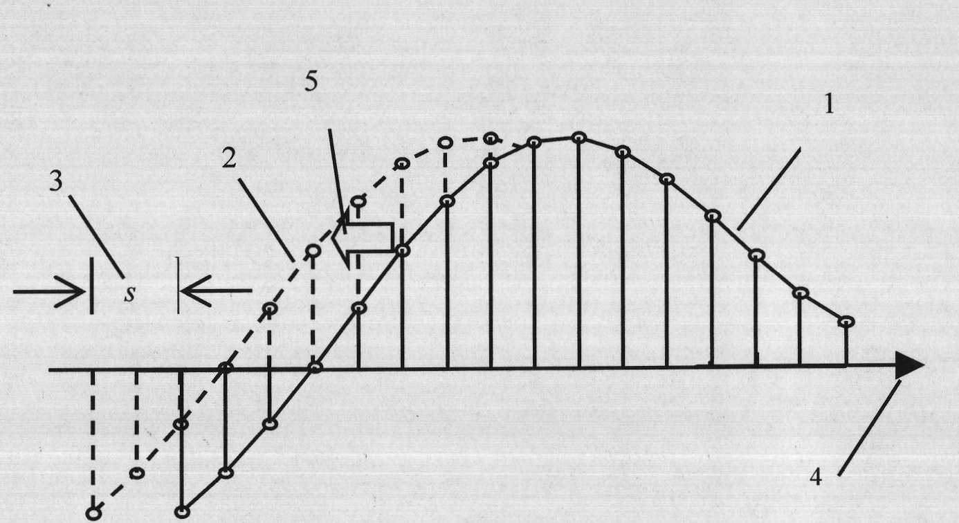
The invention relates to a phase unwrapping method based on a shearing principle, which comprises the steps of: 1, firstly, carrying out light field shearing interference in a computer; 2, reducing the occurrence frequency of under sampling with a shear algorithm, i.e. dividing two-dimensional holographic representation light compounding field by the shear light filed thereof to obtain a new light field and calculating the phase of the new light field to obtain the gradient of the phase along the transverse or horizontal direction of the two-dimensional holographic representation light compounding field; and 3, calculating the phase of the two-dimensional holographic representation light compounding field by using the gradient of the phase along the transverse or horizontal direction of the two-dimensional holographic representation light compounding field. In the invention, a shearing interference principle is introduced into the reconstruction of the phase of a digital holographic representation light field, manual translation is carried out on the digital holographic representation light field in the computer to realize transverse and horizontal shearing interference to obtain nearly unwrapped shearing phase distribution, and a corresponding phase reconstruction algorithm is established. The phase reconstruction result obtained by using the method is better than that obtained by using the traditional method.

Description

technical field [0001] The invention relates to the technical field of phase reconstruction of a reproduction light field in digital holography, in particular to a phase unwrapping method based on a shearing principle. Background technique [0002] Holography can record and reproduce the phase of the light field, so it has unique advantages in optical detection. With the advancement of computer, CCD, CMOS and other photoelectric conversion device technologies, digital holography and its detection technology, which replace traditional holographic photosensitive plates with CCD and other photoelectric conversion devices, are becoming a research hotspot and have been widely used. In this field, after using digital holography to obtain a high-quality reproduced light field, how to obtain the phase of the reproduced light field through phase unwrapping operation is an important research content. Because in digital holography and holographic interference detection technology, in ...

Claims


Application Information

Patent Timeline
IPC IPC(8): G03H1/22
Inventor 钱晓凡
Owner KUNMING UNIV OF SCI & TECH
Learn More