
Receiver for a wire-free communication system

a wire-free communication and receiver technology, applied in the field of wire-free communication systems, can solve the problems of severe loss of performance in comparison to linear (ideal) receivers, distortion of transmission signals, and noise, and achieve the effect of reducing power consumption, reducing noise, and improving performance of receivers with limiting devices

Inactive Publication Date: 2006-01-05
INTEL CORP
View PDF16 Cites 4 Cited by
  • Summary
  • Abstract
  • Description
  • Claims
  • Application Information

AI Technical Summary

Benefits of technology

[0018] The present invention is directed to a receiver for a digital communication system, whose implementation complexity and power consumption are low, and which is suitable for both two-value digital modulation methods and for digital modulation methods with more values.
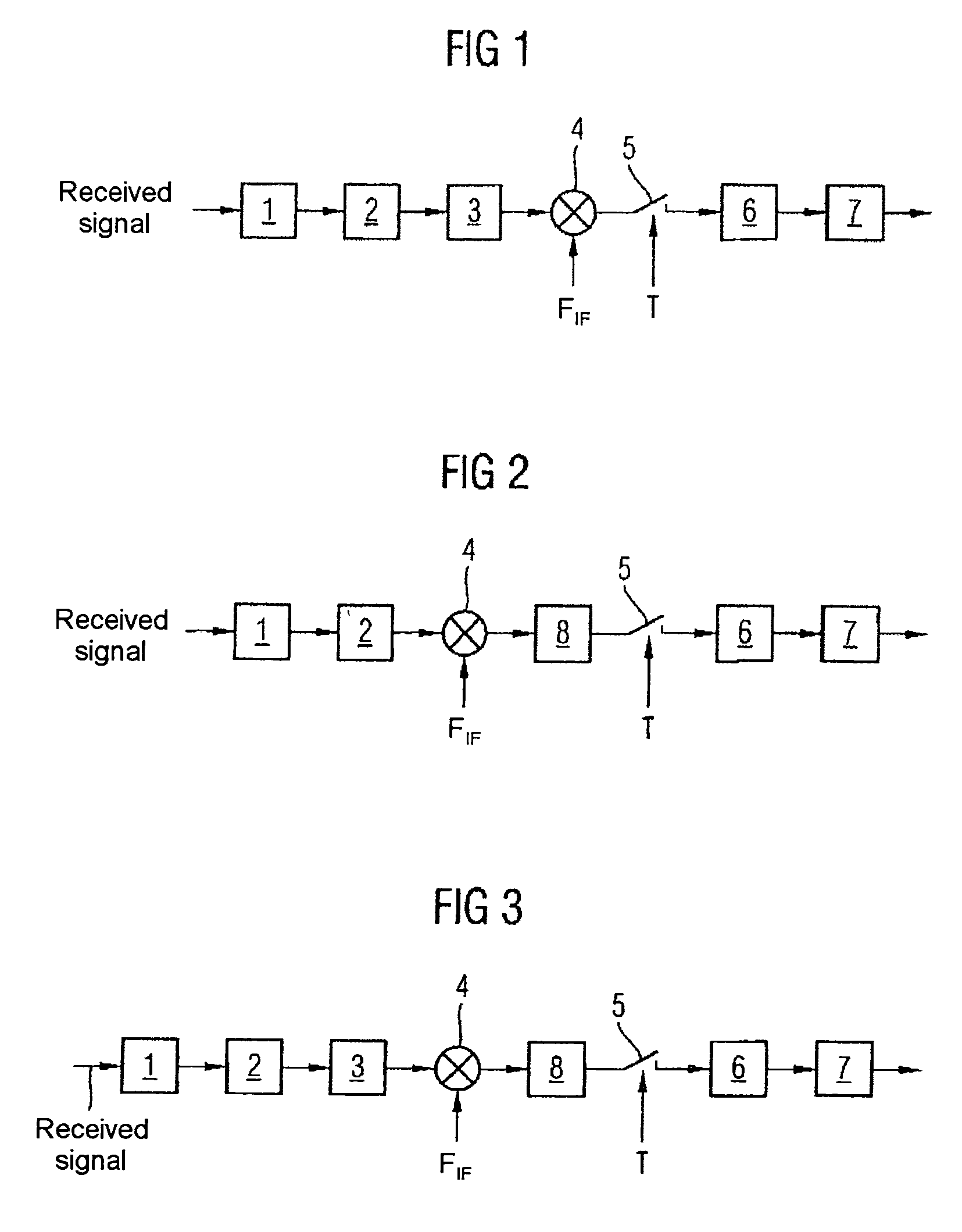
[0035] According to a further embodiment of the receiver, a sampling device for sampling the binary received signal is arranged between the second frequency conversion device and the mapping device and reduces the sampling rate of the binary received signal to a symbol clock rate of the symbols.

Problems solved by technology

The radio channel distorts the transmission signal and adds noise to it.
Investigations have shown that simply adding a limiting device to a conventional receiver for a modulation method with more values leads to a severe loss of performance in comparison to a linear (ideal) receiver.
This loss of performance may be quite considerable, particularly when subject to the influence of non-linear effects.
Since the performance loss that has been mentioned when using a receiver with a limiting device is unacceptable, a receiver with a conventional high-resolution A / D converter is used nowadays for the modulation methods with more values.
One disadvantage of the use of conventional high-resolution A / D converters is, however, that the implementation complexity is very high, and this is therefore associated with increased costs and a greater power consumption.

Method used


Image

  • Receiver for a wire-free communication system
  • Receiver for a wire-free communication system

Examples


Embodiment Construction

[0045]FIG. 1 shows a first exemplary embodiment of a receiver according to the invention, which has a matched pre-filter 1, an analogue / digital converter 2, a phase reconstruction device 3, a frequency conversion device 4, a sampling device 5, a mapping device 6 and a differential detection device 7. The analogue / digital converter 2 is a limiter or a limiting device followed by a sampler. The frequency conversion device 4 is preferably a mixer.

[0046] The pre-filter 1 is used to band-limit a received signal, which is being converted to an intermediate frequency, at one of its inputs, and to carry out the channel selection process. The pre-filter 1 reduces the performance loss that has been mentioned for digital modulation methods with more values. The pre-filter 1 preferably has a root-cosine characteristic when the pulse shaping in a transmitter is carried out by means of a root-cosine filter (matched filter). An output signal from the matched filter is preferably sampled at multip...


PUM


Abstract

The present invention is directed to a receiver for a wire-free communication system for reception of a received signal which is modulated using a digital modulation method having a first frequency conversion device for production of a frequency-converted received signal by conversion of the received signal to an intermediate frequency. The receiver further includes a pre-filter for production of a filtered received signal from the frequency-converted received signal such that the received signal is band-limited, and an analogue / digital converter for production of a binary received signal from the filtered received signal by comparison of the filtered received signal with a level threshold. In addition, the receiver includes a phase reconstruction device for production of a phase-reconstructed received signal by reproduction of the phase of the received signal from the time intervals between zero crossings of the binary received signal, and a mapping device for production of a bit sequence by mapping symbols from the phase-reconstructed received signal onto this bit sequence using the digital modulation method.

Description

REFERENCE TO RELATED APPLICATIONS [0001] This application claims the benefit of the priority date of German application DE 10 2004 028 806.2, filed on Jun. 15, 2004, the contents of which are herein incorporated by reference in their entirety. FIELD OF THE INVENTION [0002] The present invention relates in general to wire-free communication systems, and in particular to a receiver for a wire-free communication system for reception of a received signal which is modulated using a digital modulation method. BACKGROUND OF THE INVENTION [0003] A wire-free digital communication system has at least one transmitter and one receiver. The information to be transmitted from a transmitter is normally initially in the form of a bit sequence. The bit sequence is mapped in the transmitter onto symbols on a complex plane, by means of a mapping device or a mapper. The complex plane is covered by a real in-phase branch (I) and an imaginary quadrature branch (Q), and the symbols correspondingly have an...

Claims


Application Information

Patent Timeline
Patent Type & Authority Applications(United States)
IPC IPC(8): H04L27/06H04L27/00H04L27/14H04L27/233
CPCH04L27/2337
Inventor NEUBAUER, ANDREHAMMES, MARKUSBRUCKMANN, DIETER
Owner INTEL CORP
Learn More