Pedal type continuous vibration piezoelectric generating device

A power generation device, vibrating pressure technology, applied in the direction of generator/motor, piezoelectric effect/electrostrictive or magnetostrictive motor, electrical components, etc. problem, to achieve the effect of ensuring continuity

Inactive Publication Date: 2011-04-13
SHANGHAI UNIV
View PDF5 Cites 30 Cited by
  • Summary
  • Abstract
  • Description
  • Claims
  • Application Information

AI Technical Summary

Problems solved by technology

When there is no mass block at the free end of the cantilever beam, the cantilever beam can only be subjected to intermittent vibrations due to external influences, s

Method used


Image

  • Pedal type continuous vibration piezoelectric generating device
  • Pedal type continuous vibration piezoelectric generating device
  • Pedal type continuous vibration piezoelectric generating device

Examples


Embodiment 1

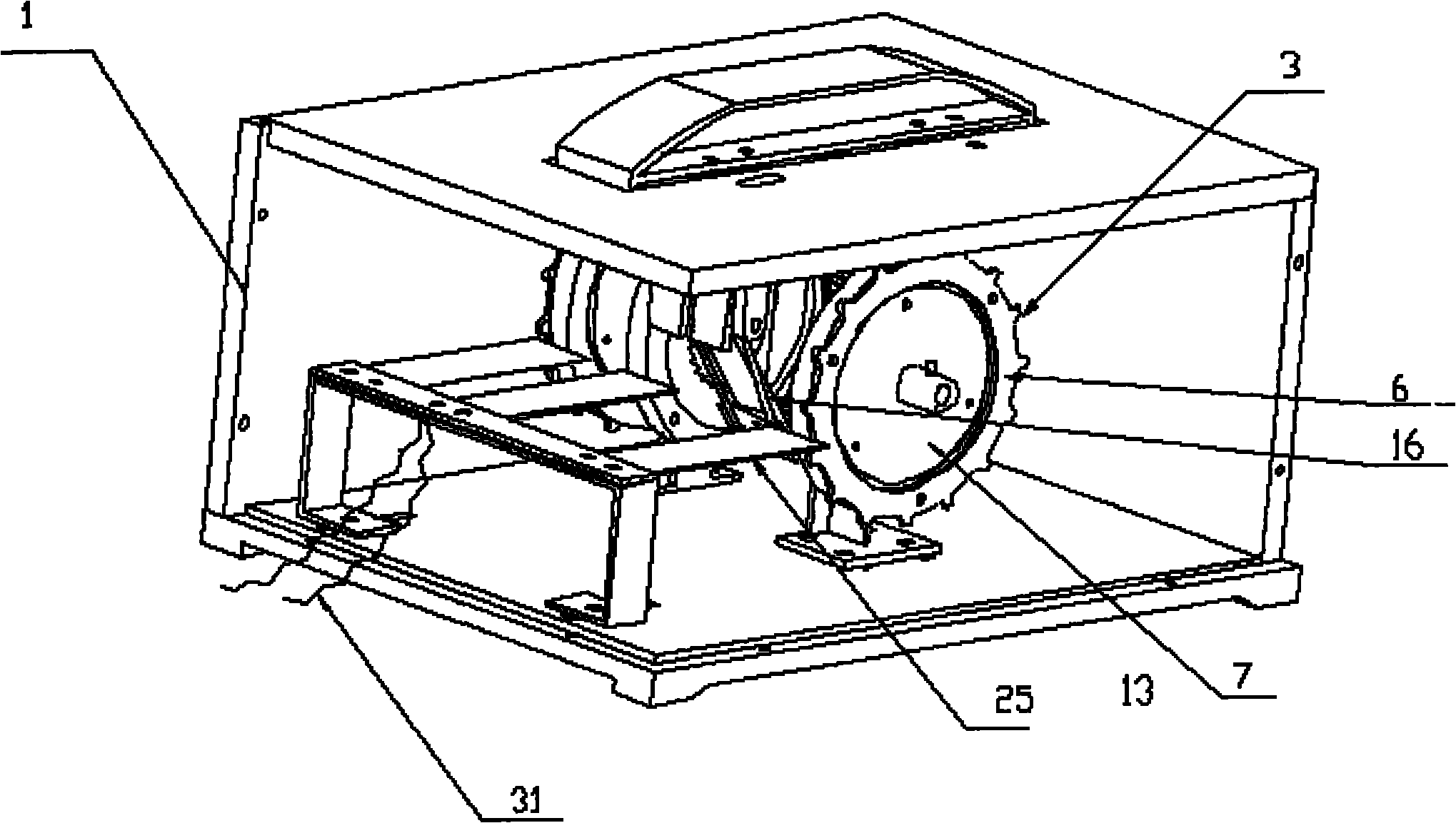
[0033] Example 1, see figure 1 , figure 2 , image 3 , Figure 4 with Image 6 The stepping type continuous vibration piezoelectric power generation device is characterized in that it includes a central opening of the upper cover of the box body. The stepping pedal is installed through a spring mechanism, and the stepping pedal is driven by a gear mechanism to drive N groups of ratchet mechanism linkage stations. In the vibrating piezoelectric generator, N is a natural number except zero.

Embodiment 2

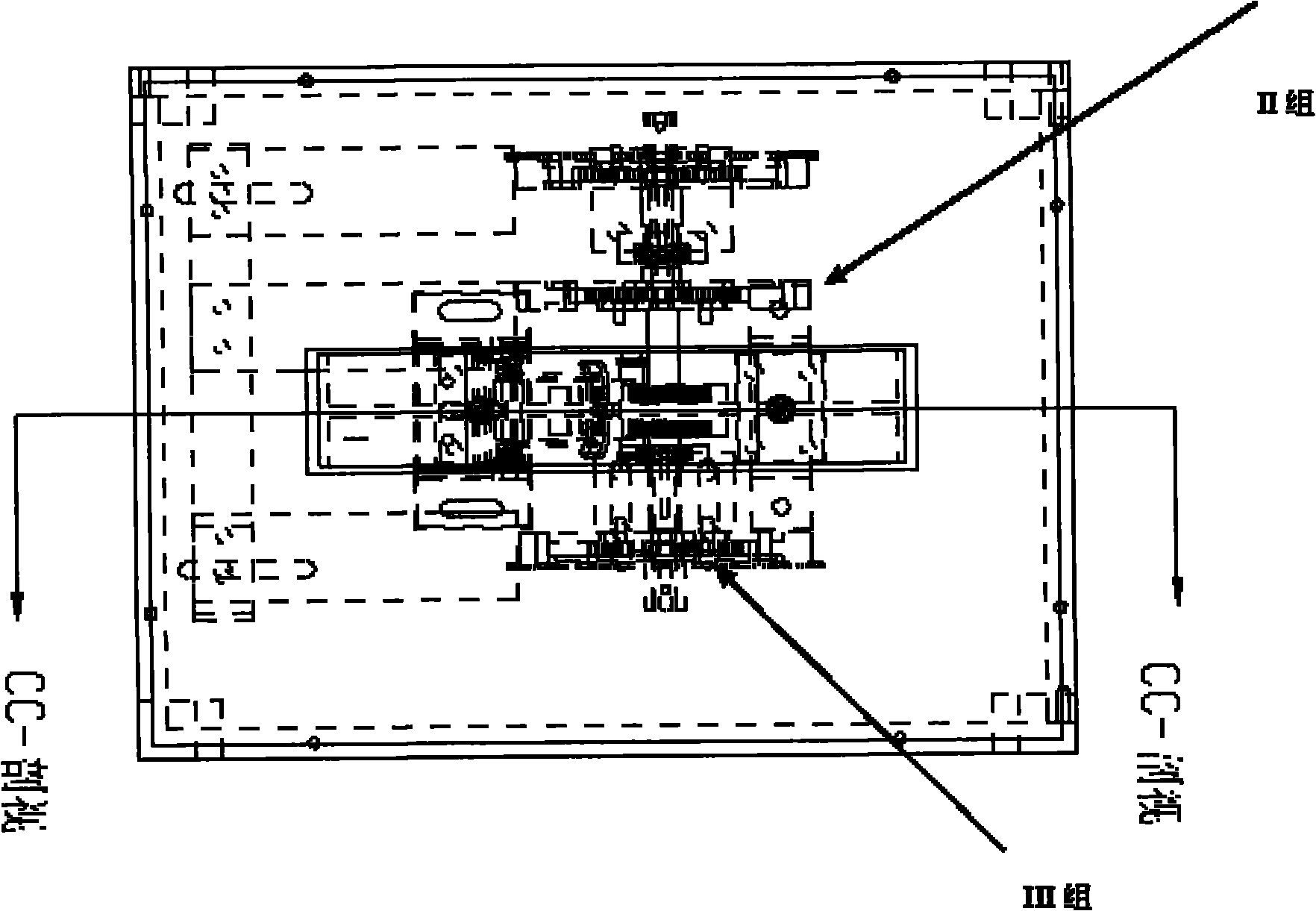
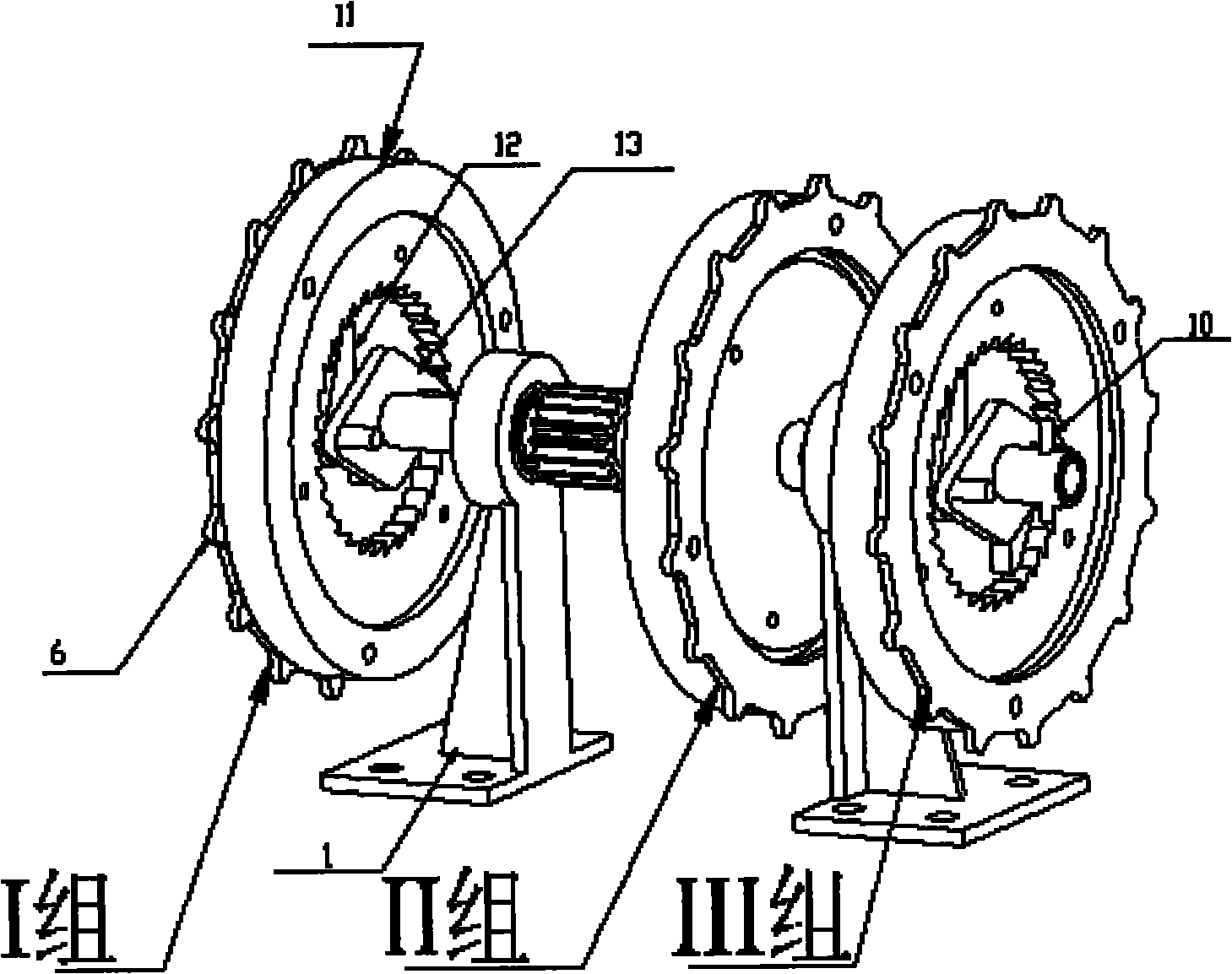
[0034] Example two, see Figure 1-Figure 11 , This pedaling type continuous vibration piezoelectric power generation device: a pedal 2 is installed above the box 1, and a spring 18, a small bearing 20, a gear mechanism 16 and a ratchet mechanism 3 are installed below the pedal 2. The spring 18 is installed directly below the two ends of the pedal 2 and the small bearing 20 is installed on the internal gear 21. The gear mechanism 16 is internally meshed with the pinion 15 on the gear shaft 8 by an internal gear 21 in a sector structure. The internal gear 21 is mounted on the lower end of the spring mechanism 23 through a pin 24. A reset torsion spring 22 is installed at both ends of the pin. When the pedal 2 is stepped down, the internal gear 21 is forced to rotate clockwise to drive the gear shaft 8, while the reset torsion spring is compressed; when the pedaling force disappears, the compressed reset torsion spring 22 resumes extension and drives the inner The gear 21 turns t...

Embodiment 3

[0035] Embodiment 3: This embodiment is the same as Embodiment 1, and the special features are:

[0036] The spring mechanism 23 is a support spring 18 installed directly below the two ends of the pedal 2. The upper end of the support spring 18 is supported on the upper flange of a guide rod 19, and the lower end is supported on a support plate 17. The support plate 17 is fixedly connected to the box body 1. The gear mechanism 16 is an internal gear 21 in a sector structure that meshes with a pinion 15 on a gear shaft 8. The internal gear 21 is mounted on the lower end of the spring mechanism 23 through a pin 24. The pin 24 A reset torsion spring 22 is installed at both ends, and a small bearing 20 is installed with the top end of the sector structure of the internal gear 21 and abuts against the lower surface of the pedal 2. When the pedal 2 is stepped down, the internal gear is forced 21 rotates clockwise to drive the gear shaft 8 while the reset torsion spring is compressed; ...


PUM


Abstract

The invention discloses a pedal type continuous vibration piezoelectric generating device. The device mainly comprises a pedal which is mounted at the position of an opening in the center of an upper cover of a box body through a spring mechanism, and the pedal drives N groups of ratchet mechanisms to link a vibration piezoelectric generator through a gear mechanism, wherein N is a natural numberexcept zero. After the pedal is stepped, acting energy is transferred to a flywheel through the gear mechanism and the ratchet mechanisms, and a pick tray is driven by the flywheel which continuouslyrotates in one direction to move a metal sheet of a cantilever beam and ensure the continuous vibration of the cantilever beam. The invention can bear repeated stepping, converts the intermittent stepping power of a stream of people into the continuous vibration of the cantilever beam, and the energized piezoelectric sheet can accordingly generate continuous electric power output so as to finallyreach the aim of effectively accumulating the electric power.

Description

Technical field [0001] The invention relates to a pedaling type continuous vibration piezoelectric power generation device, which belongs to the field of energy saving technology and energy utilization in actual engineering. Background technique [0002] Energy sources that can be used to generate electricity include wind, water, solar, nuclear, and steam. With the ever-increasing demand for energy and huge reliance on conventional energy, people realize that the development of new energy and the research of new energy-saving methods are imperative. Researchers have been committed to experimenting with new energy utilization and proposing various energy-saving methods. [0003] Some studies collect the energy of vehicles and pedestrians on the road. For example, the systems developed in this area include mechanical systems, pneumatic systems, and hydraulic systems. [0004] U.S. Pat. No. 4,238,687, a system disclosed by Martinez. This system uses turbines to generate electricity f...

Claims


Application Information

Patent Timeline
IPC IPC(8): H02N2/18
Inventor 刘树林许小勇张学红刘颖慧李玉珍刘锐王玉超宗兆辉
Owner SHANGHAI UNIV
Why Eureka
Try Eureka