Rotor for the compressor of a turbine engine comprising a centripetal air-collecting means

A technology for turbines and compressors, which is applied in the cooling of gas turbine devices, machines/engines, and engines. It can solve problems such as inability to reduce heat loss, and achieve the effects of reduced consumption rate, small width, and lower temperature.

Inactive Publication Date: 2011-04-13
SN DETUDE & DE CONSTR DE MOTEURS DAVIATION S N E C M A
View PDF5 Cites 13 Cited by
  • Summary
  • Abstract
  • Description
  • Claims
  • Application Information

AI Technical Summary

Problems solved by technology

However, such sheets do not allow for a reduction in heat loss in the central region of the cavity

Method used


Image

  • Rotor for the compressor of a turbine engine comprising a centripetal air-collecting means
  • Rotor for the compressor of a turbine engine comprising a centripetal air-collecting means
  • Rotor for the compressor of a turbine engine comprising a centripetal air-collecting means

Examples


Embodiment Construction

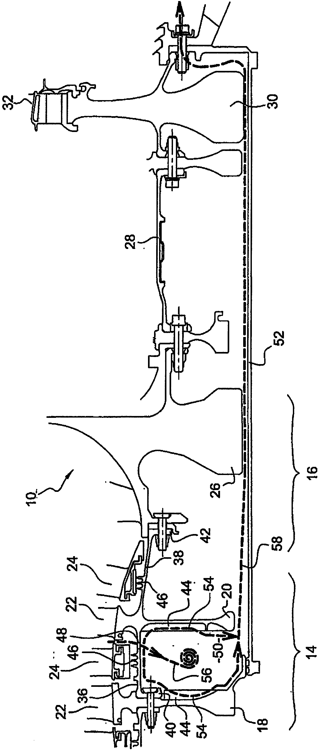
[0029] see first figure 1 , which shows part of a turbine fitted with a prior art centripetal air discharge mechanism 44,48.

[0030] The turbomachine specifically includes: a compressor, a combustion chamber and a turbine. The compressors 14 , 16 are partially shown and include an upstream module having a plurality of axial compression stages 14 and a downstream module having a centrifugal compression stage 16 . Each axial stage 14 of the compressor comprises: a rotor wheel formed by disks 18, 20 carrying blades 22 at their outer peripheries; and a nozzle 24 located downstream of the wheel and passing through an annular row of stationary nozzles Leaf formation.

[0031] The rotor disks 18 , 20 are mounted on an axis common to them and to the impeller 26 of the centrifugal stage 16 , which is itself fastened to the rotor wheel of the turbine by the inner cylindrical casing 28 of the combustion chamber. The wheel of the turbine is formed by a rim 30 which carries blades 32 o...


PUM


Abstract

The invention relates to a rotor for the compressor of a turbine engine that includes at least two coaxial discs (118, 120) carrying blades and connected together by a substantially cylindrical revolution wall (136), a centripetal air-collecting means including air passages (148) extending through the wall, and radial vanes (160) for rectifying the air flow exiting the passages in the wall, said vanes being carried by one of the discs and being substantially aligned in the radial direction with the passages of the wall.

Description

technical field [0001] The present invention relates to a centripetal air discharge mechanism in a compressor rotor of a turbomachine, such as an aircraft turboprop or turbojet. Background technique [0002] The blade wheels of the compressor rotor are connected together by walls forming generally cylindrical or frusto-conical surfaces of revolution extending coaxially between the disks. Said wall connecting the discs together may be integral with a first disc; alternatively, it may be seated and fastened at one axial end thereof to the side of the first disc, and its opposite axial end may be It includes an annular flange fastened to the second disc by means of bolt and nut type means. [0003] It is known to fit a rotor to a centripetal flow air discharge mechanism for a feed system for ventilating and / or cooling the downstream stages of the compressor and the turbine rim and possibly for cleaning the turbine. [0004] In the prior art, these air discharge mechanisms con...

Claims


Application Information

Patent Timeline
Patent Type & Authority Applications(China)
IPC IPC(8): F01D5/06F01D5/08F02C7/18
CPCF05D2260/231F05D2240/61F04D29/584F02C6/08F05B2260/231F04D29/541F04D27/0215Y02T50/675F05B2240/61F04D29/321Y02T50/60
Inventor 本杰明·帕古埃特
Owner SN DETUDE & DE CONSTR DE MOTEURS DAVIATION S N E C M A
Why Eureka
Try Eureka