Method for determining the rail pressure in a common rail system, and common rail injection system

A technology of injection system and rail pressure, which is applied in fuel injection control, electrical control, machine/engine, etc., and can solve the problems of keeping the quantity regulating valve open, unable to control the injection quantity, rail pressure rising pressure sensor, etc.

A technology of injection system and rail pressure, which is applied in fuel injection control, electrical control, machine/engine, etc., and can solve the problems of keeping the quantity regulating valve open, unable to control the injection quantity, rail pressure rising pressure sensor, etc.

CN102016271AActive Publication Date: 2011-04-13VTESCO TECH GMBH

Image

  • Method for determining the rail pressure in a common rail system, and common rail injection system
  • Method for determining the rail pressure in a common rail system, and common rail injection system
  • Method for determining the rail pressure in a common rail system, and common rail injection system

Examples


Embodiment Construction

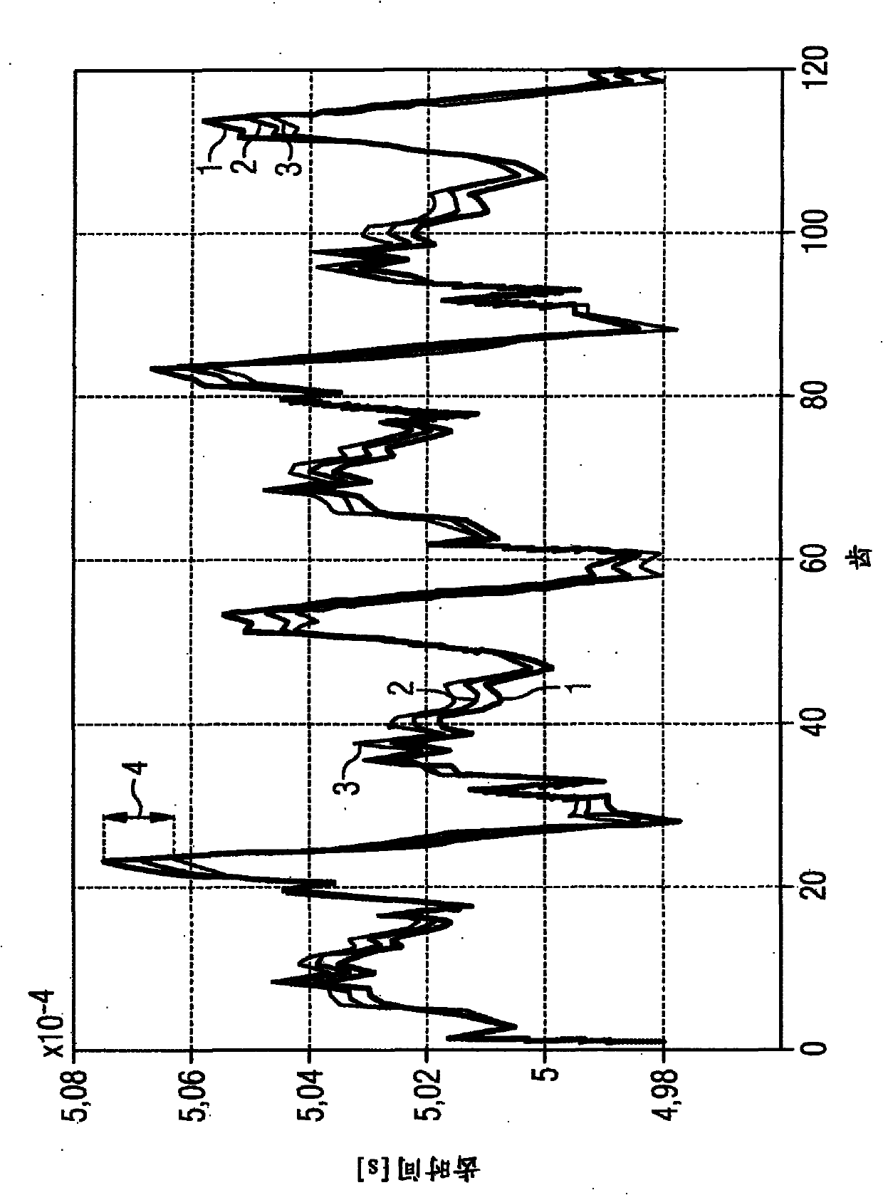
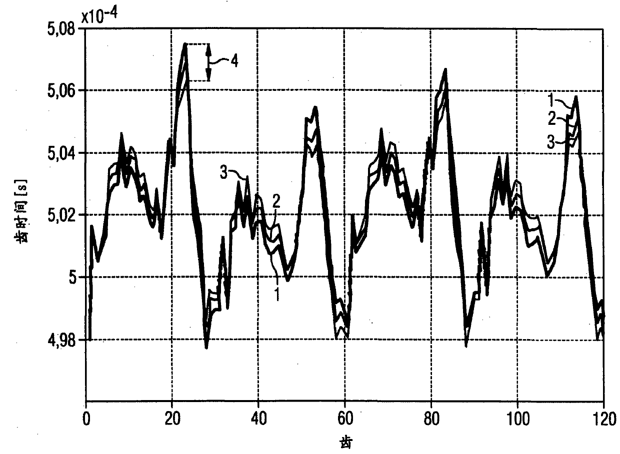
[0029] figure 1 For the inertia running phase of the internal combustion engine under three different rail pressures in the common rail fuel injection system of the internal combustion engine with 10 -4 The tooth time in seconds, where the intake pressure and average speed are the same values ​​under these three different operating conditions. Along the X-axis are the four working strokes of a four-stroke engine. figure 1 It describes the absolute tooth time, that is, the time measured by the sensor when two adjacent teeth on the sensor wheel connected to the crankshaft pass by the sensor. The sensor wheel in the example shown has 60 teeth. In the four phases of a working cycle, 120 teeth pass the sensor. The curve labeled 1 shows the tooth time at an intake pressure of 160Mpa, curve 2 corresponds to 100Mpa, and curve 3 corresponds to 20Mpa. In the example shown, the two-piston high-pressure pump is coupled to the crankshaft with a transmission ratio of 1:1, so that the hi...


PUM


Abstract

The present invention relates to a method for determining the rail pressure in a common rail system of an internal combustion engine, wherein at least one measurement variable is determined, which is a measure for the angular speed of a crankshaft movement of the internal combustion engine, and the rail pressure is derived from said measurement variable, or from a variable derived from the measurement variable. The invention further relates to methods that are based thereon for controlling an injection volume and for controlling a rail pressure, and to a corresponding common rail injection system.

Description

technical field [0001] The invention relates to a method for determining the rail pressure in a common rail injection system of an internal combustion engine, a method for controlling the injection quantity of a common rail injection system based on the rail pressure, a method for controlling the rail pressure in a common rail injection system method, and a common rail injection system for an internal combustion engine. Background technique [0002] In a common rail injection system, a plurality of injectors (injection valves), generally all injection valves of the respective internal combustion engine, are supplied with fuel via a common delivery system. The fuel is kept under pressure in this case by a common high-pressure pump. For this purpose, fuel can be delivered from the tank to the high-pressure pump via the fuel delivery pump. In order to regulate the pressure, referred to here as the rail pressure, in the common delivery system of the common rail injection syste...

Claims


Application Information

Patent Timeline
13 Apr 2011
Publication
CN102016271A
IPC
F02D41/14; F02D41/38
CPC
F02D2041/223; F02D41/123; F02D2200/1002; F02D2250/31; F02D41/1497; F02D41/222; F02D2200/0604; F02D41/3836
Inventors
U·容; J·拉德茨基