Air conditioner and refrigerant amount determining method
A technology of air conditioning and refrigerant quantity, which is applied in the direction of refrigerators, refrigeration components, refrigeration and liquefaction, etc., which can solve problems such as the reduction of refrigerant quantity, the increase of compressor temperature, and the decrease of compressor reliability, so as to improve the judgment accuracy and maintain detection The effect of maintaining accuracy and reliability
- Summary
- Abstract
- Description
- Claims
- Application Information
AI Technical Summary
Problems solved by technology
Method used
Image
Examples
no. 1 approach
[0151] Structure of the air conditioning device
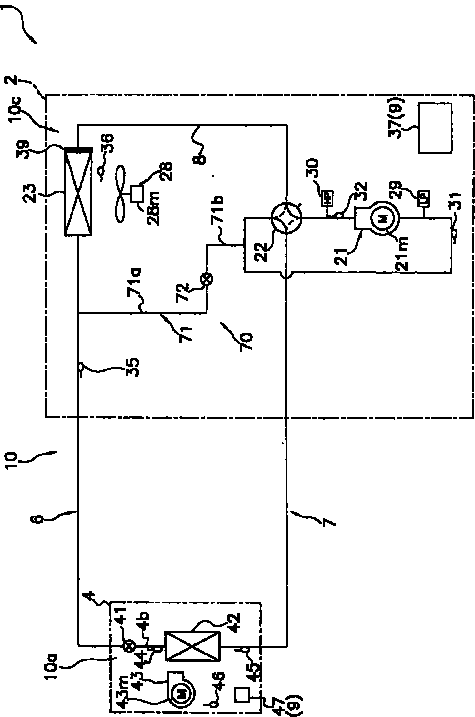
[0152] figure 1 It is a schematic configuration diagram of the air-conditioning apparatus 1 according to the first embodiment of the present invention.
[0153] The air-conditioning apparatus 1 is an apparatus used for cooling and heating indoors of a building or the like by performing a vapor compression refrigeration cycle operation.
[0154] The air conditioner 1 mainly includes an outdoor unit 2 as a heat source unit, two indoor units 4 as utilization units connected in parallel to it, and a liquid refrigerant as a refrigerant communication pipe connecting the outdoor unit 2 and the indoor unit 4. The connection pipe 6 and the gas refrigerant connection pipe 7. That is, the vapor compression refrigerant circuit 10 of the air-conditioning apparatus 1 according to the present embodiment is configured by connecting the outdoor unit 2 , the indoor unit 4 , the liquid refrigerant communication pipe 6 , and the gas refrigerant...
no. 2 approach
[0380] Structure of the air conditioning device
[0381] Figure 28 It is a schematic configuration diagram of the air-conditioning apparatus 201 according to the second embodiment of the present invention.
[0382] The air conditioner 201 is an apparatus used for cooling and heating indoors of a building or the like by performing a vapor compression type refrigeration cycle operation.
[0383] The air conditioner 201 mainly includes one outdoor unit 2 as a heat source unit, a plurality of (two in this embodiment) indoor units 4 and 5 as utilization units connected in parallel to it, the outdoor unit 2 and the indoor unit 4, 5 as the liquid refrigerant connecting pipe 6 and the gas refrigerant connecting pipe 7 connected as the refrigerant connecting pipe. That is, the vapor compression refrigerant circuit 210 of the air-conditioning apparatus 201 of this embodiment is configured by connecting the outdoor unit 2 , the indoor units 4 and 5 , the liquid refrigerant communicat...
no. 3 approach
[0611] In the above-mentioned first and second embodiments and the air-conditioning apparatuses 1 and 201 of their modified examples, a case where the present invention is applied to a configuration capable of switching between refrigerant operation and heating operation has been described as an example.
[0612] However, the present invention is not limited thereto, for example Figure 48 As shown in the air-conditioning apparatus 301 of the present embodiment shown, if a cooling operation is performed for a certain air-conditioned space while a heating operation is performed for another air-conditioned space, it can also be compared with the air-conditioned spaces in the house where the indoor units 4 and 5 are installed. Requirements are met, and the present invention is applicable to a structure capable of simultaneously operating cooling and heating.
[0613] Structure of the third embodiment
[0614] The air conditioner 201 of this embodiment mainly includes a pluralit...
PUM
 Abstract
Description
Claims
Application Information
 - R&D
- Intellectual Property
- Life Sciences
- Materials
- Tech Scout
- Unparalleled Data Quality
- Higher Quality Content
- 60% Fewer Hallucinations
Browse by: Latest US Patents, China's latest patents, Technical Efficacy Thesaurus, Application Domain, Technology Topic, Popular Technical Reports.
© 2025 PatSnap. All rights reserved.Legal|Privacy policy|Modern Slavery Act Transparency Statement|Sitemap|About US| Contact US: help@patsnap.com


