Frit sealing using direct resistive heating

A resistance heating element and glass frit technology, applied in the direction of circuits, electric light sources, electrical components, etc., can solve the problems of stress, delamination, and crack formation of seals, and achieve firm seals, uniform temperature distribution, and small residual stress Effect

Inactive Publication Date: 2013-09-18
CORNING INC
View PDF5 Cites 0 Cited by
  • Summary
  • Abstract
  • Description
  • Claims
  • Application Information

AI Technical Summary

Problems solved by technology

However, the direct resistance heating method described in this document has various deficiencies and needs to be improved
One of the drawbacks is uneven heating of the frit material between the substrates, which can lead to stress and crack formation in the seal, potentially causing delamination

Method used


Image

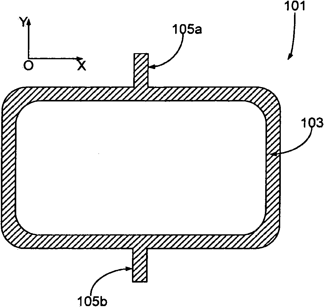
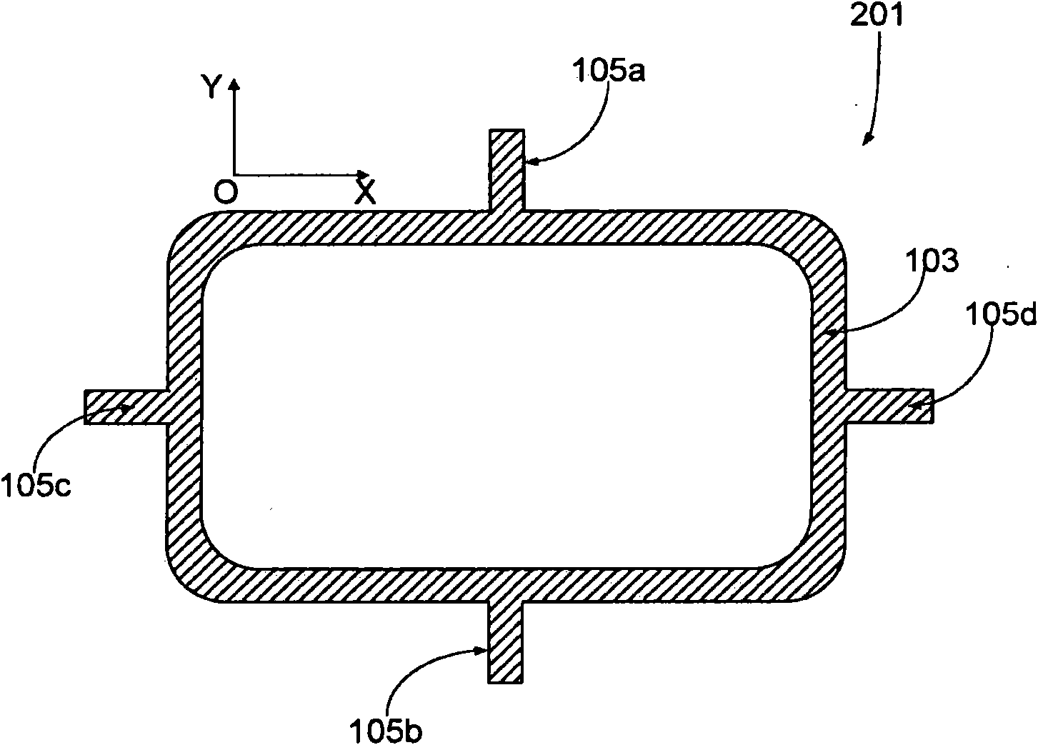
  • Frit sealing using direct resistive heating
  • Frit sealing using direct resistive heating
  • Frit sealing using direct resistive heating

Examples


Embodiment

[0085] or 2-5 mil (0.05-0.13 mm) thick flakes of the alloy were purchased from commercial sources such as Ed Fagan Inc. The designed heating element pattern is cut from the sheet by photochemical etching or micro laser cutting. Photochemical etching is suitable for very precise, burr-free, high-quality cuts. The pattern is pre-oxidized at approximately 550° C. for approximately 2-5 minutes; the pattern can be held with a magnetic plate (e.g. a fixture) because with All are soft magnets. The frit is dispensed on one side of the pattern by screen printing or hydraulically and then pre-cured. In the case of screen printing, masking is required. The heating element with frit applied on both sides is sandwiched between two glass substrates with proper alignment. A frit with a top weight of about 100-150 g / mm2 is applied on the cover glass. The heating elements are connected to a DC or AC power source which can be computer programmed to control the cooling rate. Power i...


PUM


Abstract

An frit-sealed device comprising a resistive heating element having an electrically-closed-loop structure and process for frit-sealing a device by using such heating element. The element can be advantageously made of a metal such as Invar(R) and / or Kovar(R). The invention enables hermetic frit sealing with low residual stress in the seal. The invention is particularly advantageous for hermetic sealing of OLED display devices.

Description

[0001] This application claims priority to US Patent Application Serial No. 12 / 074144, filed February 29, 2008. technical field [0002] The present invention relates to sealing devices using frit material. In particular, the invention relates to the hermetic sealing of devices comprising chambers by direct resistive heating of frit materials, and to devices so sealed. The invention can be used, for example, for the sealing of OLED devices. Background technique [0003] Many optical and / or electrical devices include a chamber defined by a plurality of components within which additional optical and / or electronic components are housed and protected. Depending on the components included, it may be necessary to hermetically seal the chambers of the devices to prolong the useful life of the devices. Hermetic sealing can be challenging. [0004] For example, OLED (Organic Light Emitting Diode) displays are about to appear in the next-generation display market, but hermetic seal...

Claims


Application Information

Patent Timeline
Patent Type & Authority Patents(China)
IPC IPC(8): H01L51/52H05B33/04
CPCH01L51/5237H10K71/40H10K59/8722H10K71/233H10K71/13H10K71/16H05B33/04H10K50/8426
Inventor 王文超
Owner CORNING INC
Why Eureka
Try Eureka