
Drawing transmission device of spinning frame

A transmission device and spinning frame technology, applied in spinning frames, drafting equipment, continuous winding spinning frames, etc., can solve the problems of twist transfer and spinning tension instability, achieve reliable technical support, and easy to change production. , The effect of improving twist transfer and stabilizing spinning tension

Inactive Publication Date: 2011-04-20
JINGWEI TEXTILE MASCH CO LTD
View PDF9 Cites 4 Cited by
  • Summary
  • Abstract
  • Description
  • Claims
  • Application Information

AI Technical Summary

Problems solved by technology

[0003] The technical problem to be solved by the present invention is to provide a spinning frame drafting transmission device, which solves the problems of twist transmission and spinning tension instability by changing the spinning angle, reduces yarn breakage, and improves spinning speed. quality

Method used


Image

  • Drawing transmission device of spinning frame
  • Drawing transmission device of spinning frame
  • Drawing transmission device of spinning frame

Examples


Embodiment Construction

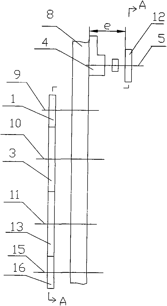
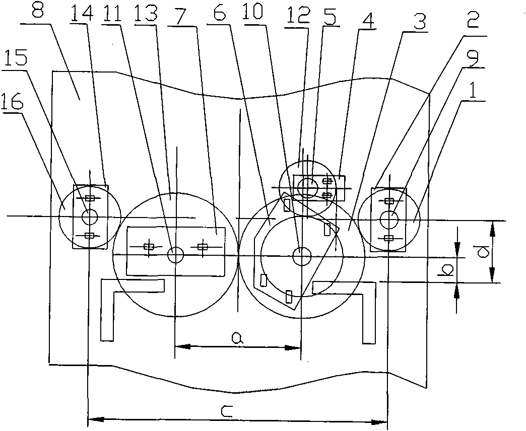
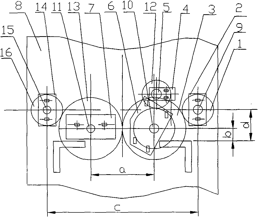
[0009] A drafting transmission device for a spinning frame, which includes a right front roller gear 1, a right front roller bearing seat 2, a right butterfly tooth 3, a roller transmission bearing seat 4, a middle rear roller transmission shaft 5, a double bearing seat 6, and a left butterfly tooth bearing seat 7. Head wall panel 8, right front roller head section shaft 9, right butterfly tooth shaft 10, left butterfly tooth shaft 11, middle and rear roller transmission gear 12, left butterfly tooth 13, left front roller bearing seat 14, left front roller head section shaft 15 , front left roller gear 16, right front roller bearing seat 2, roller transmission bearing seat 4, double bearing seat 6, left butterfly tooth bearing seat 7, left front roller bearing seat 14 are arranged on the head wall plate 8; right front roller bearing seat 2 is provided with There is a shaft 9 of the right front roller head, and a right front roller gear 1 is arranged on the shaft 9 of the right ...


PUM


Abstract

The invention relates to a drawing transmission device of a spinning frame. A right front roller bearing seat (2) is provided with a right front roller head one-section shaft (9); a right front roller gear (1) is arranged on the right front roller head one-section shaft (9); a right butterfly tooth shaft (10) is provided with right butterfly teeth (3); the right front roller gear (1) and the right butterfly teeth (3) are meshed; a left butterfly tooth shaft (11) is provided with left butterfly teeth (13), and the right butterfly teeth (3) are meshed with the left butterfly teeth (13); a left front roller head one-section shaft (15) is provided with a left front roller gear (16) which is meshed with the left butterfly teeth (13); and a roller transmission bearing seat (4) is provided with a middle rear roller transmission shaft (5) which is provided with a middle rear roller transmission gear (12), the right butterfly teeth (13) are connected with the middle rear roller transmission gear (12) by a gear. By utilizing the device, the problems of instable degree transfer and spinning tension are solved, yarn breaks are reduced, and spinning quality is improved.

Description

technical field [0001] The invention belongs to a component of a textile machine, and in particular relates to a spinning frame drafting transmission device. Background technique [0002] At present, the FK501 silk spinning frame can only spin silk, and the length of silk is 80-200 mm. With the adjustment of the market industrial structure, many silk manufacturers require to change to spinning cotton, and the length of cotton fiber is 40-60 mm. The height from the center of the former front roller to the car surface is 105 millimeters, the horizontal distance between the center of the front rollers on the left and right sides is 710 millimeters, and the angle between the drafting plane and the horizontal plane is 50 °. If the original drafting transmission device is used to spin cotton, the spinning angle is not conducive to the transfer of twist, the tension is unstable, and there are many ends broken, which is easy to cause damage to the yarn and the spinning quality is po...

Claims


Application Information

Patent Timeline
Patent Type & Authority Applications(China)
IPC IPC(8): D01H1/22D01H5/32
Inventor 冯招梅刘志勇陈红岩吴苹张炎生张新民
Owner JINGWEI TEXTILE MASCH CO LTD
Learn More