Eureka AIR delivers breakthrough ideas for toughest innovation challenges, trusted by R&D personnel around the world.

Continuous wall forming machine of underground cement soil impermeable wall

A technology of anti-seepage wall and wall forming machine, applied in the direction of earth mover/shovel, construction, etc., can solve the anti-seepage effect and the reduction of wall strength, uneven surface, uneven density, unable to guarantee the quality of the wall, etc. problems, to achieve the effect of improving the degree of freedom and cutting ability, quality balance, and equipment mobility.

Inactive Publication Date: 2011-04-20
陶为
View PDF6 Cites 8 Cited by
  • Summary
  • Abstract
  • Description
  • Claims
  • Application Information

AI Technical Summary

Problems solved by technology

For example, the SMW construction method, the underground continuous wall made by such machinery and methods is to form a wall through partial overlap between adjacent stirring piles. The thickness of the wall is uneven, the surface is uneven, and the density is uneven. The important thing is The uncertainty of the overlapping part causes the anti-seepage effect and the strength of the wall to decrease; and, due to the limitation of mechanical equipment, the construction depth is shallow, which cannot meet the requirements of some deeper walls; at the same time, construction machinery that is not as deep as the same height Stable and easy to dump; the mechanical movement of the crawler type movement is not stable, and it is easy to produce direction displacement and deviation during the movement process, which cannot guarantee the quality of the wall

Method used


Image

  • Continuous wall forming machine of underground cement soil impermeable wall
  • Continuous wall forming machine of underground cement soil impermeable wall
  • Continuous wall forming machine of underground cement soil impermeable wall

Examples


Embodiment Construction

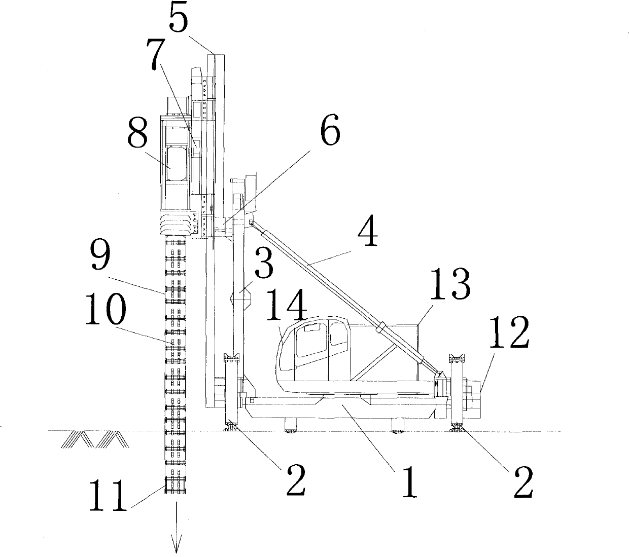
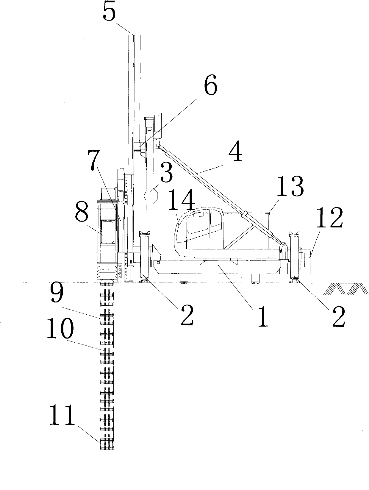
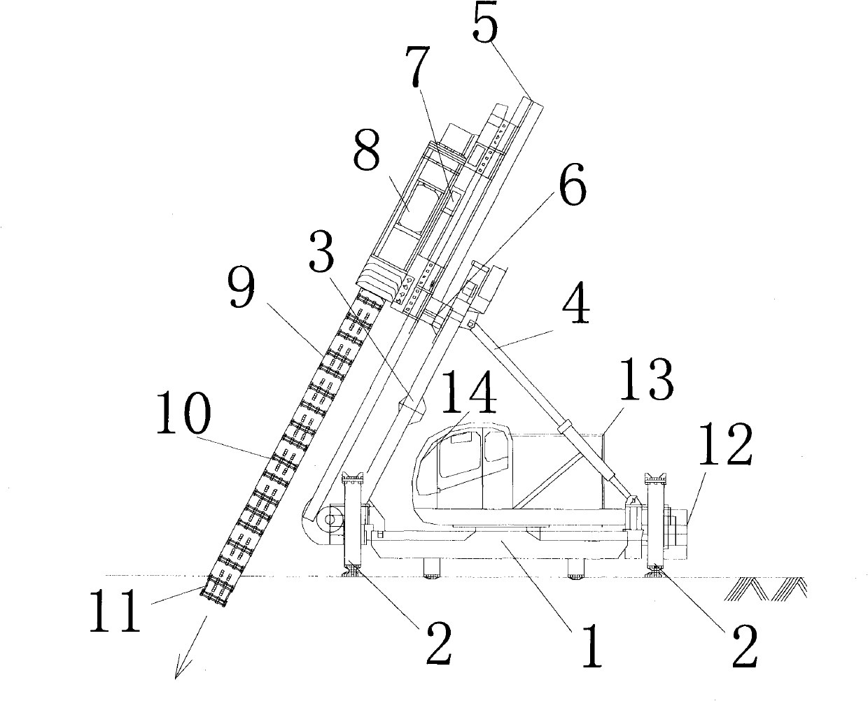
[0021] exist figure 1 Among them, the mechanical chassis (1) and the hydraulic support (2) constitute a walking-type moving mechanism, the frame (3) and the tilt adjustment rod (4) are installed on the mechanical chassis (1), and the frame (3) passes through the tilt adjustment rod (4) To achieve a vertical or inclined state, install a vertical guide rod (5) and a horizontal drive cylinder (6) on the frame (3), and make the vertical guide rod (5) horizontal on the frame (3) through the horizontal drive cylinder (6). Movement, vertical drive cylinder (7) and cutter drive mechanism (8) are installed on the vertical guide rod (5), cutter drive mechanism (8) and cutter combination box (9) and cutter combination chain (10) and cutter head ( 11) are connected, and move up and down on the vertical guide rod (5) through the vertical drive cylinder (7), and the tool combination chain (10) surrounding the tool combination box (9) on both sides is in the tool drive mechanism ( 8) and th...


PUM


Abstract

The invention relates to a continuous wall forming machine of an underground cement soil impermeable wall. A machine chassis and a hydraulic support form a walking travel mechanism, a frame and an oblique adjusting rod are arranged on the machine chassis, the frame is adjusted to be in a perpendicular or oblique position through the oblique adjusting rod, and a vertical guide rod and a horizontal drive cylinder are arranged on the frame. A cutter drive mechanism and a cutter combination box are connected with a cutter combination chain and a cutter head, and move up and down along the vertical guide rod through a vertical drive cylinder. The cutter combination chain surrounding the two sides of the cutter combination box moves around a position between the cutter drive mechanism and the cutter head. Soil layers are cut and agitated by blades fixed on the cutter combination chain. A non-fence impermeable wall having excellent impermeable effect is really built through the machine, and the continuous impermeable wall has the advantages of uniform texture, accurate advance direction, better impermeable effect and simple technology. The continuous wall forming machine can be used for digging downwards, cutting soil layers and building the cement soil wall in one step.

Description

technical field [0001] The invention relates to a continuous wall forming machine for underground cement-soil anti-seepage walls, especially capable of horizontally cutting and stirring the in-situ soil in the form of walking and moving, and is applied in fields such as water-stop curtains to form an underground anti-seepage wall with high anti-seepage performance . Background technique [0002] At present, the vast majority of underground anti-seepage wall water-proof curtains are "fences" formed by stirring pile columns to achieve the purpose of water-proof and anti-seepage of building foundation pits, embankments and underground buildings. For example, the SMW construction method, the underground continuous wall made by such machinery and methods is to form a wall through the partial overlap between adjacent stirring piles. The thickness of the wall is uneven, the surface is uneven, and the density is uneven. The important thing is The uncertainty of the overlapping part...

Claims


Application Information

Patent Timeline
IPC IPC(8): E02F5/02E02F5/14
Inventor 陶为
Owner 陶为
Why Eureka
Eureka Blog
Learn More