Stepless speed changer

A technology of continuously variable transmission and speed change mechanism, which is applied in the direction of gear transmission, belt/chain/gear, mechanical equipment, etc., can solve the problems of complex structure, low power and troublesome control of the continuously variable transmission, so as to extend the mileage between overhauls. , high average speed, easy maintenance effect

Inactive Publication Date: 2011-04-20
吴志强
View PDF4 Cites 10 Cited by
  • Summary
  • Abstract
  • Description
  • Claims
  • Application Information

AI Technical Summary

Problems solved by technology

[0002] At present, the commonly used continuously variable transmissions are designed according to the principles of friction and hydrostatics, etc., and the power they can transmit is not large, and the efficiency is not high; In addition, these continuously variable transmissions are complex in structure, cumbersome to control, and need to be realized through expensive materials and precise manufacturing, so the cost is high

Method used


Image

  • Stepless speed changer
  • Stepless speed changer
  • Stepless speed changer

Examples


Embodiment 1

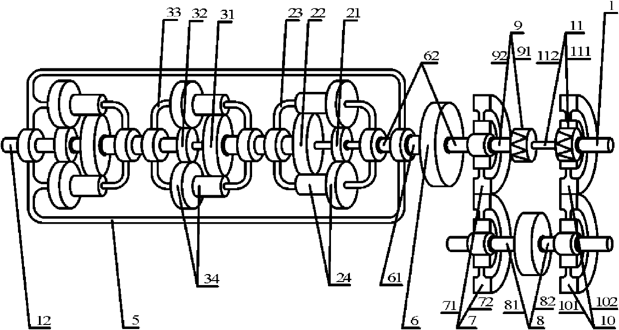
[0027] Such as figure 1As shown in , a continuously variable transmission includes an input shaft 1, a coupling frame 5, a transmission mechanism 6, an input gear pair 7, a coupling 8, a fixed one-way clutch 9, an output gear pair 10, a one-way clutch 11, an output shaft 12. The input end 91 of the fixed one-way clutch 9 is connected to a fixed element other than the present invention. Between the input shaft 1 and the output shaft 12, there are sequentially connected confluence units 2 composed of planetary rows and two The diversion unit 3, the diversion unit 2 includes the first diversion input element 21, the diversion output element 22, the second diversion input element 23, the diversion planetary gear 24, and the diversion unit 3 includes the diversion input element 31, the first The diversion output element 32, the second diversion output element 33, the diversion planetary gear 34, the confluence unit 2 is connected with the first confluence input element 21, the conf...

Embodiment 2

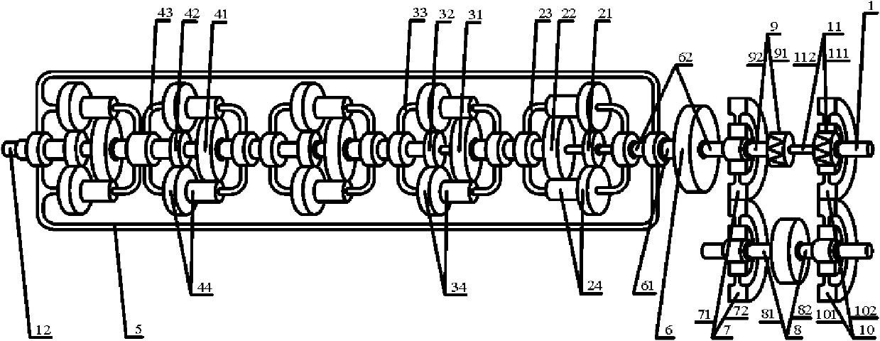
[0036] Such as figure 2 As shown in , it includes an input shaft 1, an output shaft 12, a transmission mechanism 6, an input gear pair 7, a torque converter 8, a fixed one-way clutch 9, an output gear pair 10, and a one-way clutch 11. The input end 91 of the clutch 9 is connected to a fixed element other than the present invention, and the input shaft 1 and the output shaft 12 are provided with a confluence unit 2 composed of a planetary row, two diversion units 3 and two The return unit 4, the return unit 4 includes a return input element 41, a first return output element 42, a second return output element 43, and a return planetary gear 44. The confluence unit 2 cooperates with the first reflow planetary gear 24 The confluence input element 21, the confluence output element 22, and the second confluence input element 23 are connected, the confluence output element 22 of the confluence unit 2 is connected with the diversion input element 31 of the first diversion unit 3, and...

Embodiment 3

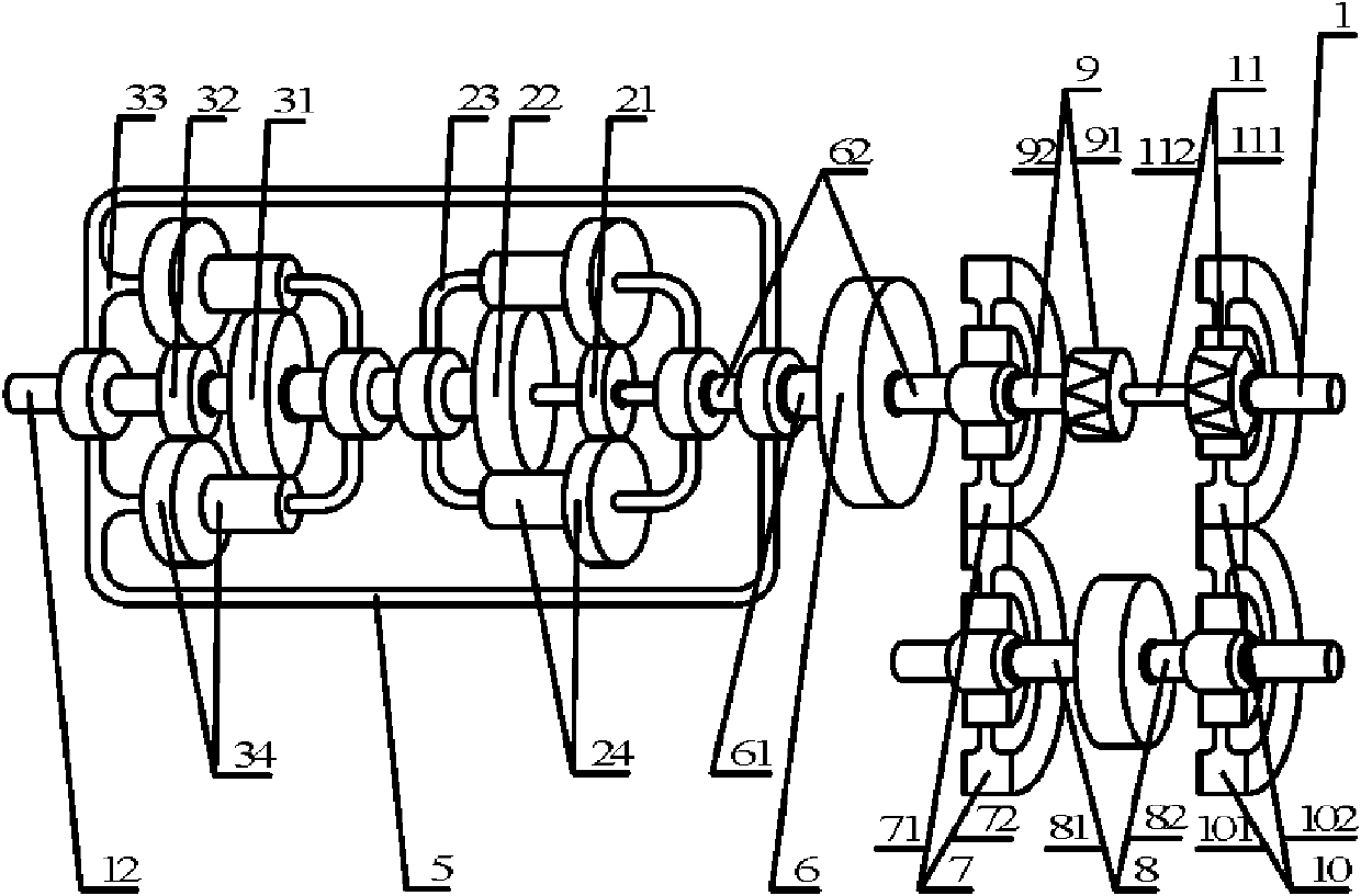
[0042] Such as image 3 As shown in , the present embodiment just replaces the two branching units 3 selected by the first embodiment with the same branching unit 3, and the branching input element 31 of this branching unit 3 is the branching input of each branching unit 3 of several branching units 3 Element 31, and is the branching input element 31 of first branching unit 3; The first branching output element 32 of this branching unit 3 is the first branching output element 32 of each branching unit 3 of several branching units 3; The first branching output element 32 of this branching unit 3 Two split flow output elements 33 are the second split flow output element 33 of each split flow unit 3 of several flow split units 3, and are the second split flow output element 33 of the last split flow unit 3, the connection object of each element replaced is the same as the original replaced one The connection object of each component remains unchanged, and its working principle an...


PUM


Abstract

The invention provides a stepless speed changer which is technically characterized in that a confluence output component 22 is connected with a first shunt input component 31, and each shunt input component 31 of the rest is connected with a last second shunt output component 33 matched with the shunt input component 31; each first shunt output component 32 is connected with an output shaft 12, and a connecting frame 5 is connected with the final second shunt output component 33, a plurality of components outside the stepless speed changer and the input end 61 of a speed changing mechanism 6; the output end 62 of the speed changing mechanism 6 is connected with a second confluence input component 23, an input gear 71 of an input gear pair 7 and the output end 92 of a fixed one-way clutch 9, and an output gear 72 of the input gear pair 7 is connected with the input end 81 of a connector 8; and the output end 82 of the connector 8 is connected with an input gear 101 of an output gear pair 10, an output gear 102 of the output gear pair 10 is connected with the input end 111 of a one-way clutch 11, and the output end 112 of the one-way clutch 11 is connected with a first confluence input component 21 and an input shaft 1.

Description

technical field [0001] The invention belongs to the field of transmissions, more specifically, it is a transmission for various ground vehicles, ships, railway locomotives, engineering machinery, various aerospace, aircraft, metallurgy, mining, petroleum, chemical industry, light industry, food, textile , Lifting and transporting machinery, machine tools, robots and military CVTs. Background technique [0002] At present, the commonly used continuously variable transmissions are designed according to the principles of friction and hydrostatics, etc. The power it can transmit is not high, and the efficiency is not high; Expensive materials and sophisticated manufacturing are required to achieve this, and thus the high cost. Contents of the invention [0003] The invention overcomes the deficiencies of the prior art and provides a continuously variable transmission that prolongs the service life of the engine and the transmission system, has simple structure, convenient ope...

Claims


Application Information

Patent Timeline
Patent Type & Authority Applications(China)
IPC IPC(8): F16H3/76
Inventor 吴志强
Owner 吴志强
Why Eureka
Try Eureka