Lower-suction range hood

A technology for range hoods and range hoods, which is applied in the fields of oil fume removal, household heating, lighting and heating equipment, etc. It can solve the problems of ceiling kitchen space pollution, smoke pipes are easy to crack and leak, and the ceiling is deformed and unsightly. Occupies the space of the hanging cabinet, convenient for packaging and transportation, and has the effect of beautiful appearance

Inactive Publication Date: 2011-04-20
翁家瑜 +1
View PDF5 Cites 3 Cited by
  • Summary
  • Abstract
  • Description
  • Claims
  • Application Information

AI Technical Summary

Problems solved by technology

[0002] The existing household range hoods have the following problems that cannot be solved: 1. Loud noise (close to the ears of the cooking staff); 2. Low suction rate, and the fumes permeate the room; 3. Difficult and inconvenient cleaning of oil stains; 4. , Obvious black oily smoke discharges polluted air; 5. The smoke exhaust pipe is located at the top, occupying the space of the hanging cabinet. The oil stained inside the

Method used


Image

  • Lower-suction range hood
  • Lower-suction range hood
  • Lower-suction range hood

Examples


Embodiment 1

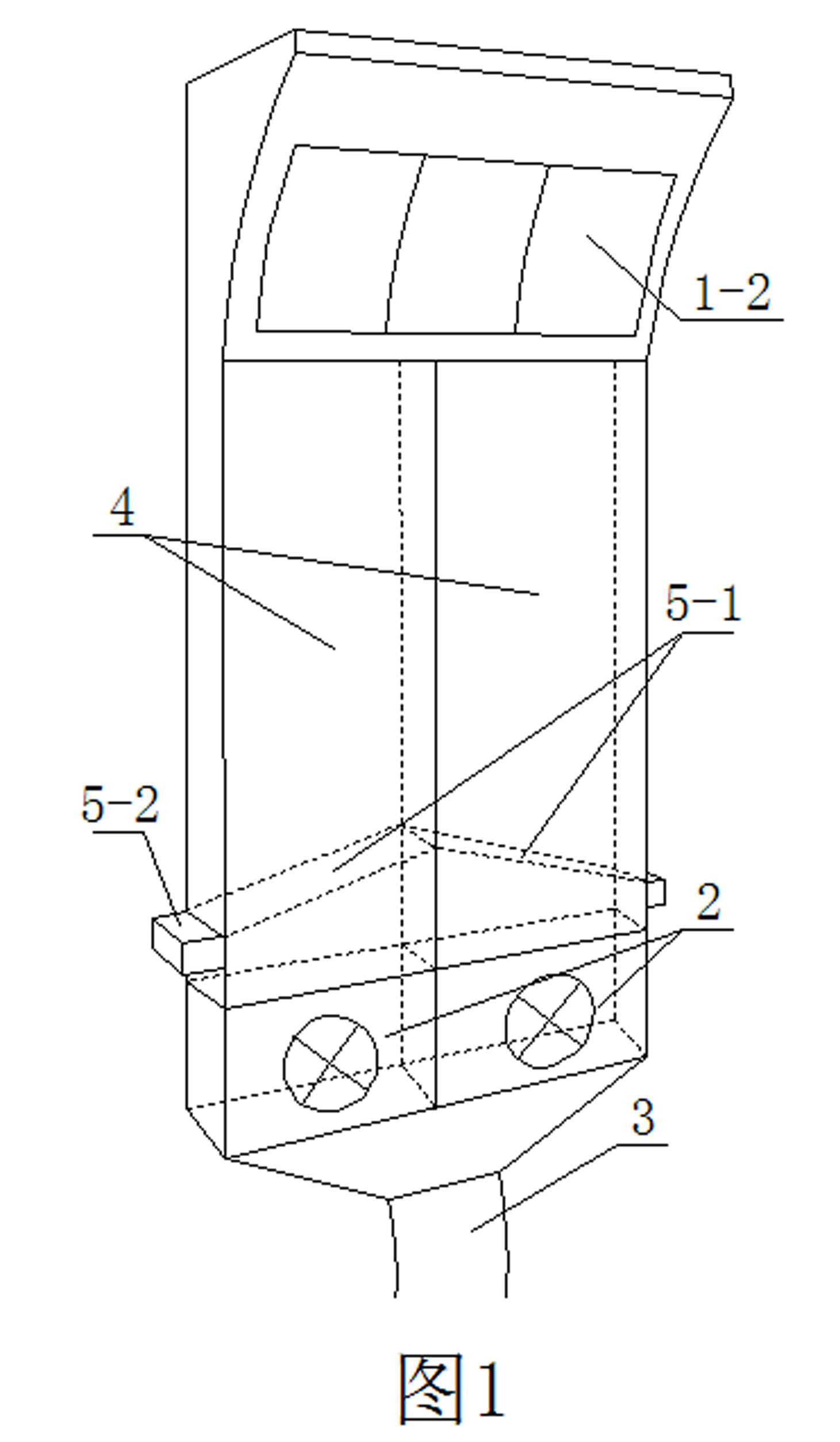
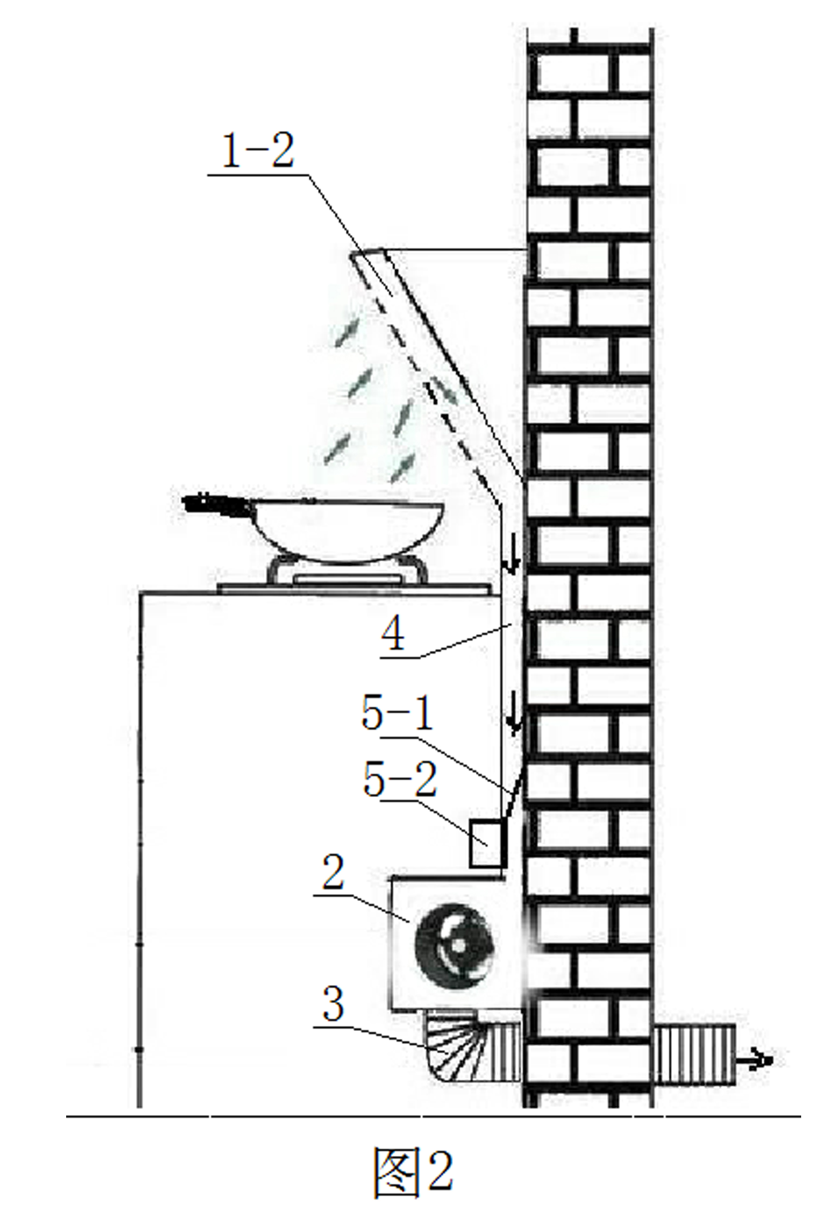
[0023] like figure 1 and figure 2 Shown is a schematic diagram of an embodiment of a lower suction range hood provided by the present invention, which includes an oil suction hood arranged above or on the side of the stove, an air extraction device 2 arranged below the oil suction hood, connecting the oil suction hood The connection channel 4 with the air extraction device 2 and the exhaust channel 3 connected with the air outlet of the air extraction device 2 .

[0024] Described air extraction device 2 is located at the bottom of the stove, and it includes more than one independently controlled air extraction motor, each air extraction motor is connected with the oil suction hood through an independent connection channel 4, or multiple air extraction motors are connected through a shared The connecting channel 4 is connected with the oil suction hood.

[0025] The connecting channel 4 is provided with an oil fume filtering device.

[0026] The oil fume filtering device i...

Embodiment 2

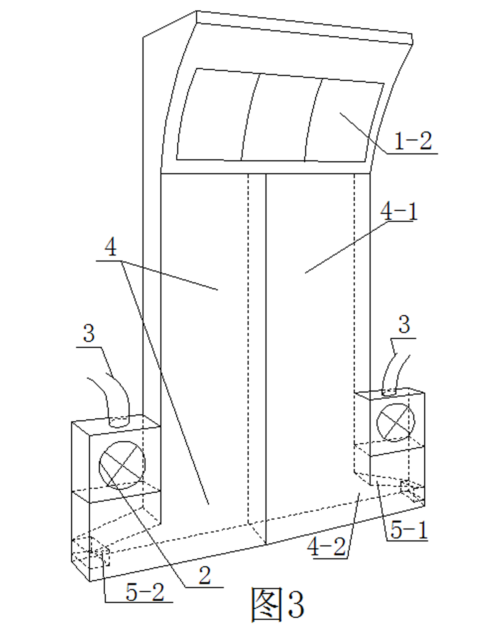
[0033] like image 3 Shown is a schematic diagram of an embodiment of Embodiment 2 of the present invention. The difference between Embodiment 2 and Embodiment 1 is that: the connecting channel 4 includes a vertical connecting channel section 4-1 and a circuitous connecting channel section 4-2 connected in sequence; The oil fume filtering device is located at the outlet end (or tail end) of the circuitous connecting channel section 4-1, the inlet end of the vertical connecting channel section 4-1 communicates with the oil suction hood, and the vertical connecting channel section The outlet end of the section 4-1 communicates with the inlet end of the circuitous connection channel section 4-2, the outlet end of the circuitous connection channel section 4-2 is higher than the inlet end, the suction device 2 and the circuitous connection channel section 4-2 connected to the outlet.

[0034] In the specific implementation, in order to facilitate the transformation of the existing...

Embodiment 3

[0036] like Figure 4 Shown is a schematic diagram of embodiment 3 of the present invention, the difference between embodiment 3 and embodiment 1 is: the oil suction hood is a hood type oil suction hood 1-1; the connecting channel 4 is near the upper side of the stove Have a plurality of oil suction smoke through holes 4-3. The hood type range hood 1-1 can adopt the cover body form of an existing hood type range hood. In order to facilitate cooking, a condiment rack can be installed on the connecting channel 4.


PUM


Abstract

The invention relates to a lower-suction range hood, comprising a smoke exhaust hood arranged above or at side top of a stove, a suction device arranged below the smoke exhaust hood, a connection passage for connecting the smoke exhaust hood and the suction device and a vent passage connected with an air outlet of the suction device, wherein the suction device is arranged below the stove so that a suction motor is far from ears of cooking staff with relatively small noise, the noise can be smaller if the suction device is arranged in a cabinet below the stove; (2) fewer circuit and less accessories are arranged in the smoke exhaust hood which is easy to clean; (3) the structure is rational, the smoke exhaust hood, the connection passage and the suction device are separately connected with each other, so that the product is convenient to package and transport, the influence to fitment is avoided, the wall cupboard space cannot be occupied and the appearance is beautiful; the connection passage can be composed of a plurality of pipelines so that the change to old kitchen is convenient.

Description

technical field [0001] The invention relates to a down suction range hood. Background technique [0002] The existing household range hoods have the following problems that cannot be solved: 1. Loud noise (close to the ears of the cooking staff); 2. Low suction rate, and the fumes permeate the room; 3. Difficult and inconvenient cleaning of oil stains; 4. , Obvious black oily smoke discharges polluted air; 5. The smoke exhaust pipe is located at the top, occupying the space of the hanging cabinet. The oil stained inside the smoke exhaust pipe flows backwards due to gravity, and after several years of use, the smoke pipe is easy to crack and leak smoke, resulting in ceiling And the pollution of the kitchen space, the maintenance or replacement needs to dismantle the ceiling, which will easily cause the ceiling to be deformed and unsightly. However, there is an underutilized slit space of about 10 cm on the back of the stove, resulting in a waste of space. Contents of the i...

Claims


Application Information

Patent Timeline
IPC IPC(8): F24C15/20
Inventor 翁慧
Owner 翁家瑜
Why Eureka
Try Eureka