Management and control system for storage battery

A management control and battery management technology, applied in battery circuit devices, measuring electricity, current collectors, etc., can solve the problems of high maintenance cost, low work reliability, and circuit failure, and achieve the effect of convenient maintenance and maintenance.

Inactive Publication Date: 2011-04-20
ZHEJIANG UNIVERSITY OF SCIENCE AND TECHNOLOGY
View PDF4 Cites 13 Cited by
  • Summary
  • Abstract
  • Description
  • Claims
  • Application Information

AI Technical Summary

Problems solved by technology

[0004] However, in the current application of storage batteries, the actual capacity of the storage battery is not easy to determine. The user cannot know how much power has been charged after the battery is fully charged, how much power has been used after a period of use, and how much power is left, so it is impossible to determine the cap

Method used


Image

  • Management and control system for storage battery
  • Management and control system for storage battery
  • Management and control system for storage battery

Examples


Example Embodiment

[0032] Example 1

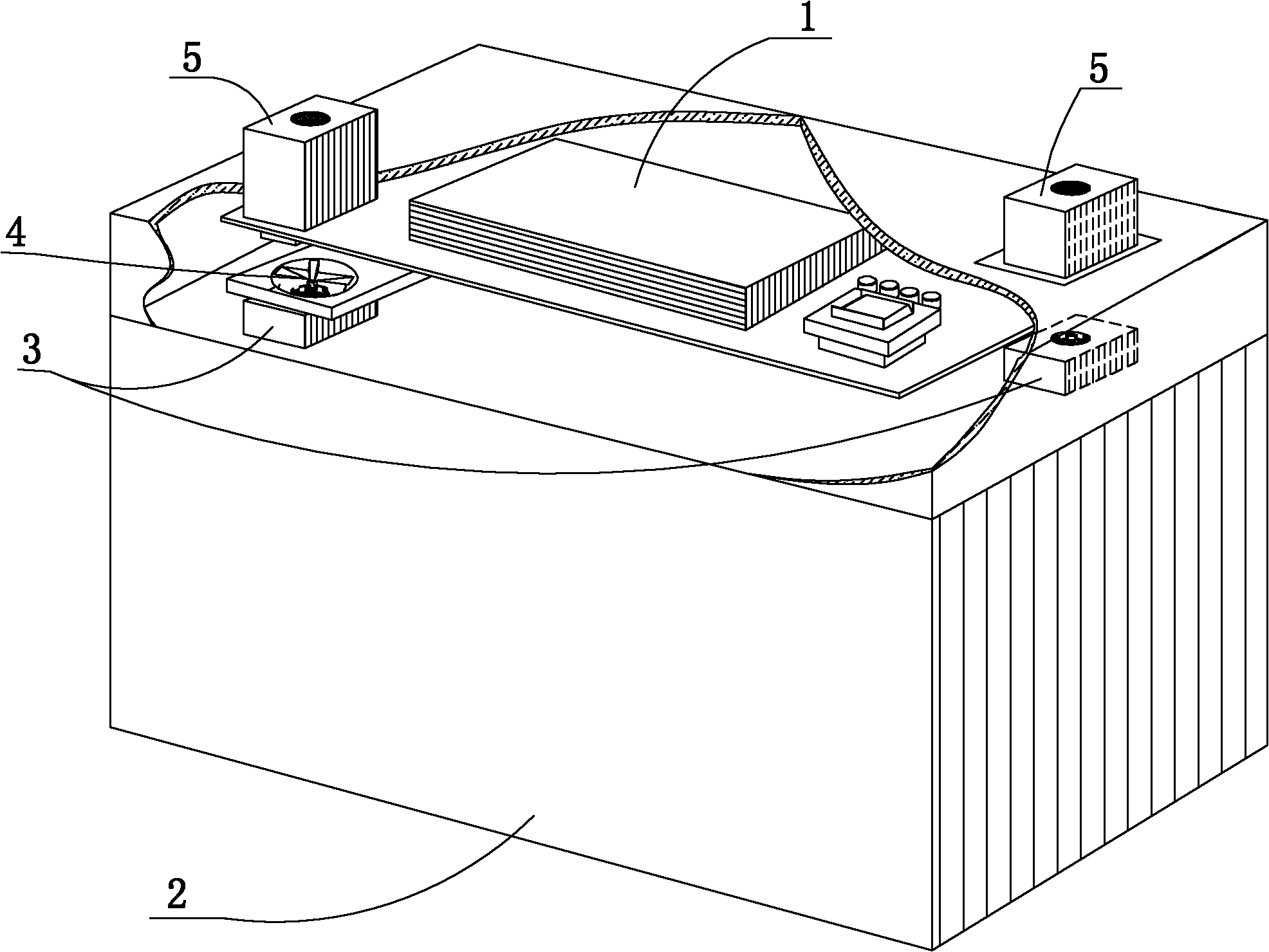
[0033] Such as figure 1 , The management control system 1 is directly embedded in the battery shell 2. There are two output terminals 5 on the management control system 1, and the two output terminals 3 of the battery and the two output terminals 5 on the management control system 1 are arranged between There is a power-off switch 4, and the two output terminals 5 on this management control system are used as the output terminals when the battery is in use, that is, when the battery and other batteries are connected in series to the power circuit, directly from the management control system Just connect the two output terminals 5 on it.

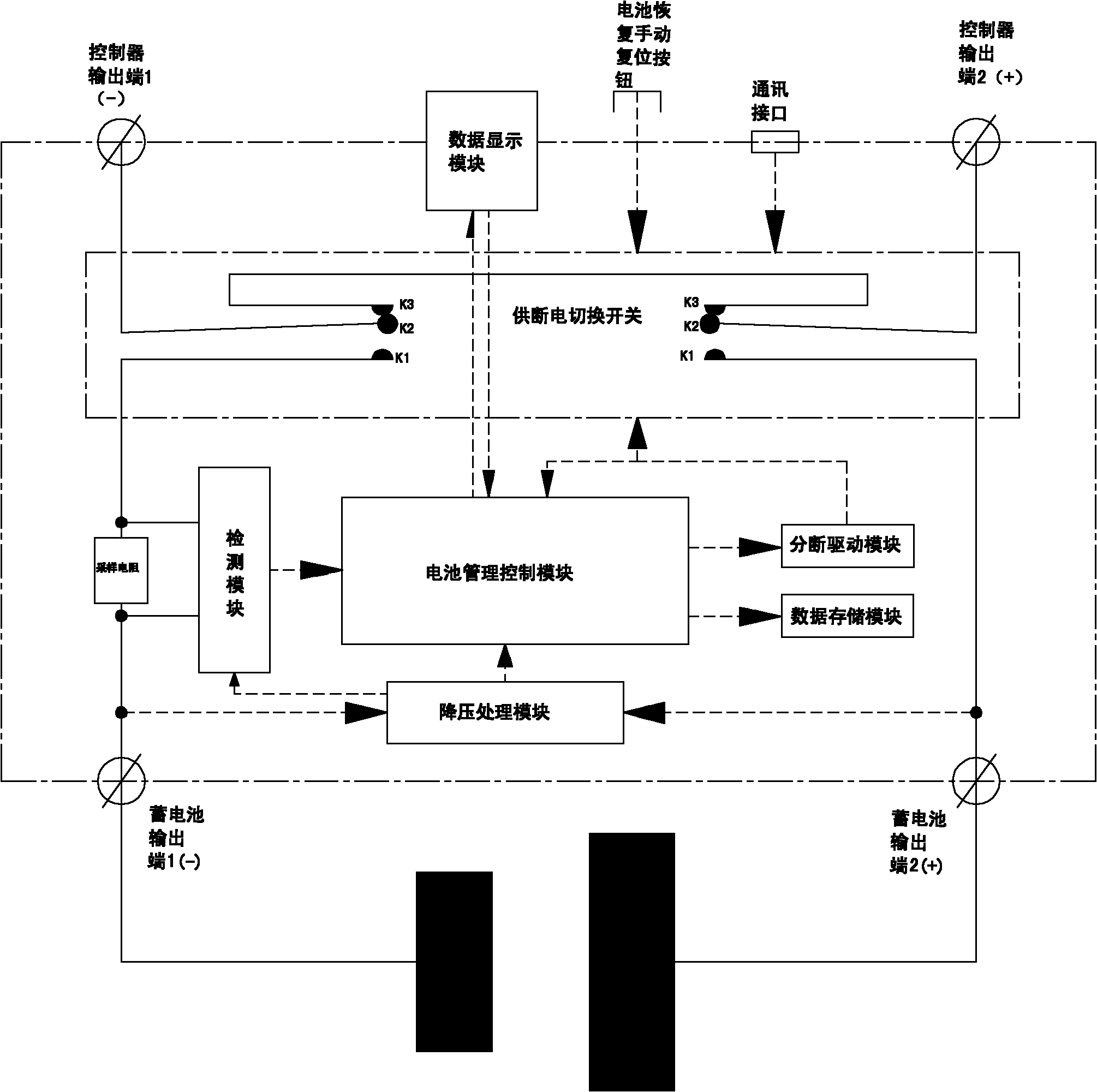
[0034] Such as figure 2 , At one output terminal of the battery, the negative (-) of output terminal 1 is connected to the sampling resistor of the detection module, the sampling resistor is connected to the A / D conversion circuit, the A / D conversion circuit is connected to the battery management control module, and the battery...

Example Embodiment

[0043] Example 2

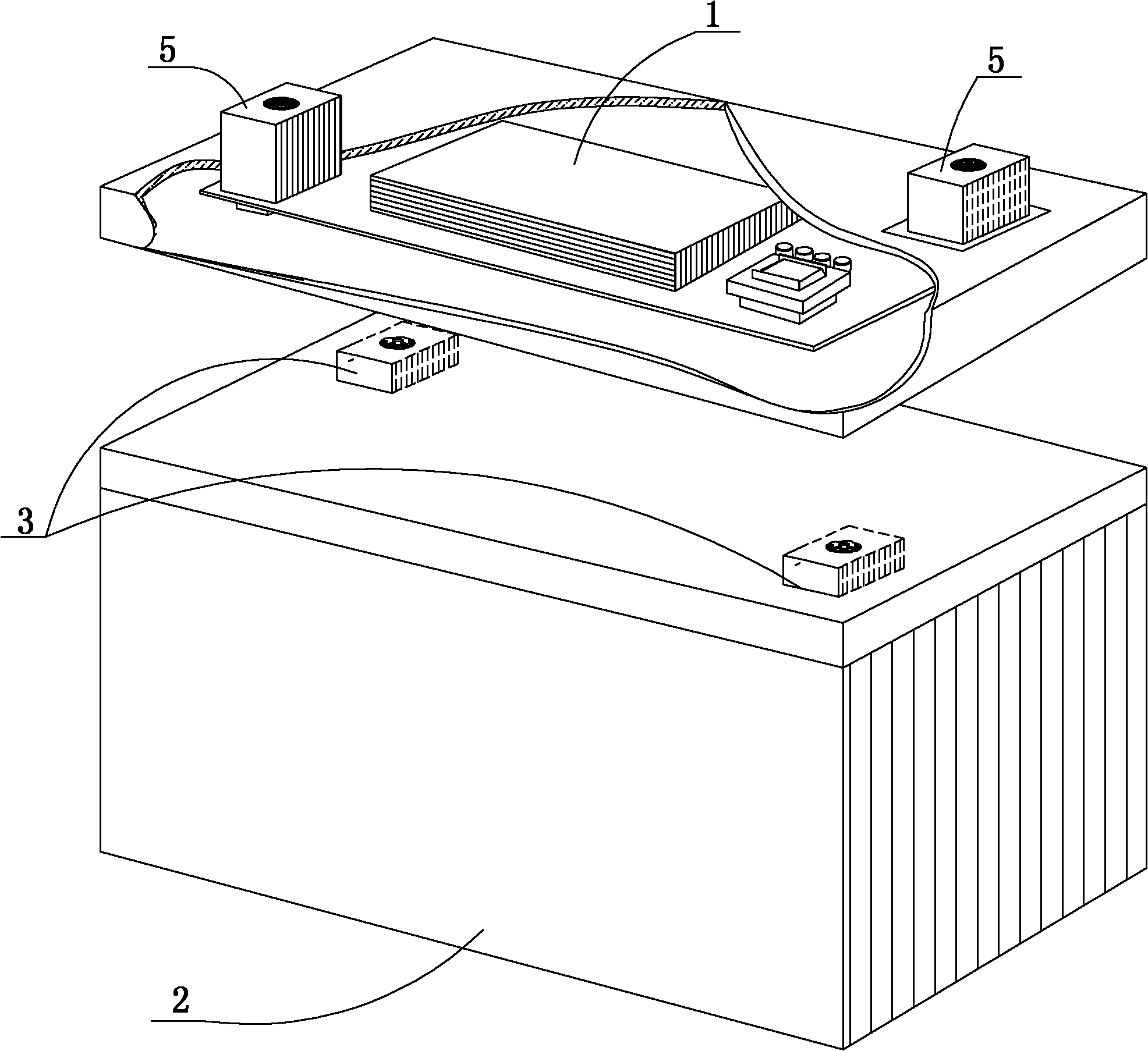
[0044] Such as image 3 Compared with Embodiment 1, the management control system of this embodiment is externally connected to the battery shell 2, and the two output terminals 3 of the battery are connected to the two output terminals 5 of the management control system 1 through wiring. The management and control system is set separately, so that it will be more convenient to replace the battery. The other technical features of this embodiment are the same as the first embodiment.

Example Embodiment

[0045] Example 3

[0046] Such as Figure 4 , 5 Compared with Embodiments 1 and 2, the power supply / disconnection switch of this embodiment is provided with only one set, which is set at one end of the battery output terminal, and the positive terminal (+) (such as Figure 4 ) Or negative terminal (-) (such as Figure 5 ), the power supply and shutdown switch also uses a relay, including two static contact arms, the first static contact arm K1, the second static contact arm K3, a movable contact arm K2, and the first static contact arm K1 is connected to an output terminal of the battery (Positive terminal (+) or negative terminal (-)), the movable contact arm K2 is used as the output terminal of the battery equipped with the management control system, and is connected to the electrical circuit, the second static contact arm K3 and the other output of the battery Terminal (negative terminal (-) or positive terminal (+)). The movable contact arm K2 is controlled by the breaking dr...


PUM


Abstract

The invention discloses a management and control system for a storage battery, which is arranged between two electrodes of a positive electrode and a negative electrode of the storage battery and two ends of an external load. Electric quantity and voltage of the storage battery are detected through a detection module, then the storage battery is subjected to charge and supply management by a battery management and control module according to a detection signal, and an alarm is given when the storage battery is invalid and the quit of the storage battery and the on and off of a total current loop are automatically or remotely controlled. The management and control system can accurately determine the rear capacity of the storage battery, thereby determining the property of the storage battery and enabling an electricity-consuming circuit to stably and reliably operate.

Description

Technical field [0001] The invention relates to a storage battery, in particular to a storage battery power management and control system. Background technique [0002] With the rapid development of modernization, energy demand growth and energy shortage are very prominent, especially the large amount of low-efficiency consumption of energy has a serious impact on environmental pollution. [0003] As the storage battery is a part of storing electric energy, people have high expectations for the safe and reliable continuous operation of the battery. For example, electric vehicles with high power requirements, electric cruise ships, backup power supplies for elevators in high-rise buildings, batteries in energy storage power supplies in solar photovoltaic power generation equipment, and backup power supplies in medical emergency services are inseparable from batteries. [0004] However, in the current application of battery, the actual capacity of the battery is not easy to determine....

Claims


Application Information

Patent Timeline
IPC IPC(8): H02J7/00G01R31/36
Inventor 陆华洋胡会明
Owner ZHEJIANG UNIVERSITY OF SCIENCE AND TECHNOLOGY
Why Eureka
Try Eureka