Optical fiber CAN bus hub and networking method thereof

A CAN bus and hub technology, applied in the field of wide-area high-speed networking, can solve the problems of communication rate drop, network congestion, inconvenient twisted-pair CAN bus subnet interface, etc.

Inactive Publication Date: 2011-04-20
HUAZHONG UNIV OF SCI & TECH +1
View PDF1 Cites 13 Cited by
  • Summary
  • Abstract
  • Description
  • Claims
  • Application Information

AI Technical Summary

Problems solved by technology

Among them: (1) the ring optical fiber CAN bus network scheme allows a very limited number of nodes (only optical fiber nodes) in the access ring, and with the increase of the number of access nodes, the communication rate drops sharply; (2 ) The optical fiber CAN bus self-healing ring network scheme also has similar problems; (3) The dual-star optical fiber CAN bus scheme allows more nodes to be connected, but like the previous two schemes, there is a signal transmission loop self-excitation that causes network congestion and inconvenient interfacing with twisted pair CAN bus subnets

Method used


Image

  • Optical fiber CAN bus hub and networking method thereof
  • Optical fiber CAN bus hub and networking method thereof
  • Optical fiber CAN bus hub and networking method thereof

Examples


Embodiment Construction

[0029] The present invention will be described in detail below in conjunction with accompanying drawings and examples.

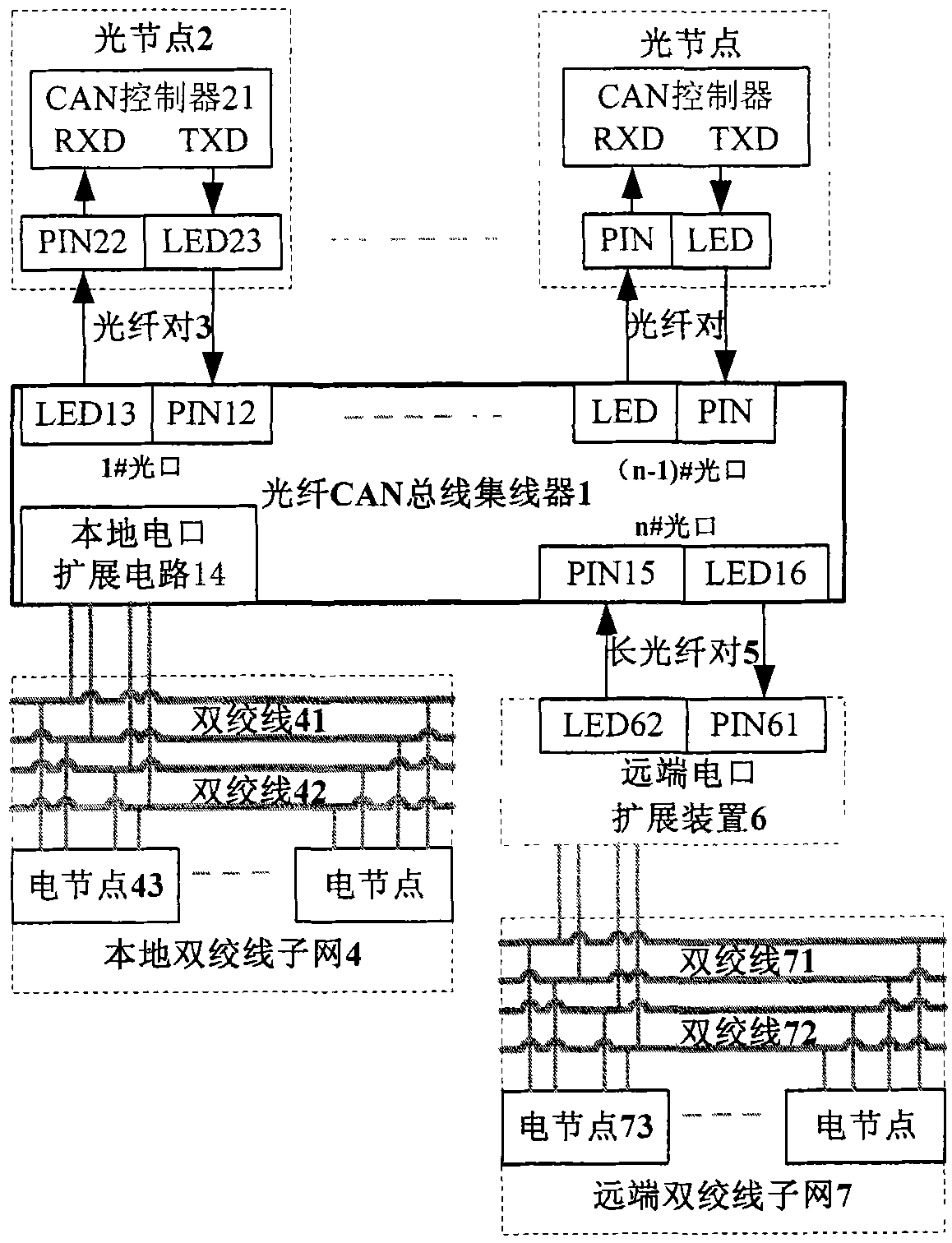
[0030] exist figure 1 In the shown wide-area CAN bus network composed of optical nodes, local electrical nodes and remote electrical nodes, the "recessive" bit and "dominant" bit sent by the node are represented as high level and low level respectively on the circuit . When transmitting in the optical fiber medium, it should be designed so that there is optical transmission corresponding to the "dominant" bit, and no optical transmission (or when not connected to the optical fiber) corresponds to the "recessive" bit.

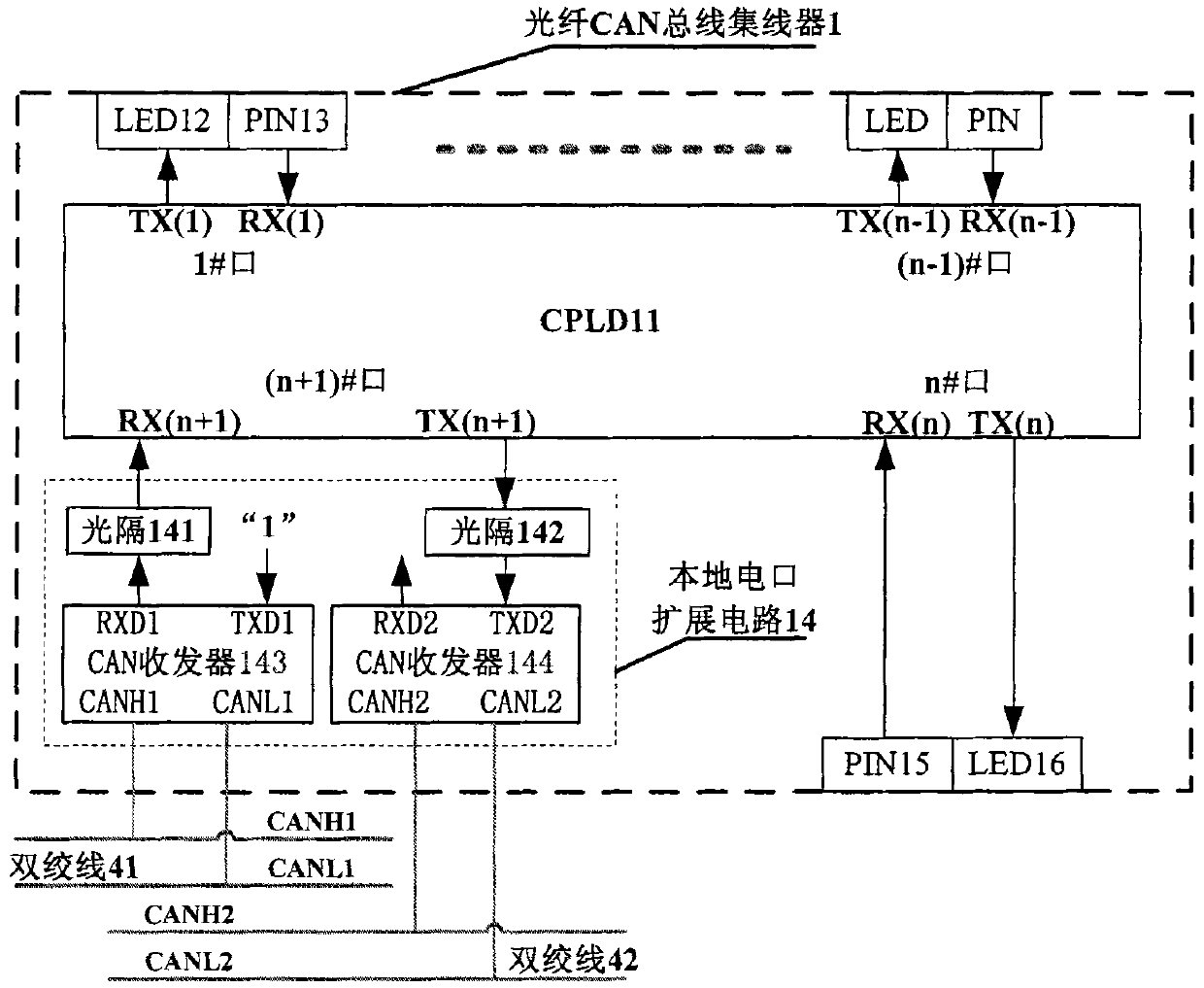
[0031] figure 2 The shown hub 1 works in the master mode, and the logic in the programmable logic device CPLD11 is designed according to the following n+1 equation groups:

[0032] TX(1), TX(2), ..., TX(n), TX(n+1) =

[0033]RX(1)&RX(2)&...&RX(n)&RX(n+1) (1)

[0034] Its meaning is to "AND" all the n+1 signals RX(1), RX(2)...RX(n), RX(n+...


PUM


Abstract

The invention discloses a networking method of an optical fiber control area network (CAN) bus hub. A main hub of an optical fiber CAN bus with n optical fiber interfaces and a local twisted pair electrical interface extension circuit and n twisted pair CAN sub-networks for connecting the main hub with n optical nodes, n secondary hubs or n remote electric interface extension devices are connected with a local twisted pair CAN sub-network to form a network; signals are transmitted, received and separated by using the optical fiber CAN bus hub which realizes a wired and function through a complex programmable logic device (CPLD) and is provided with a plurality of optical interfaces and a twisted pair electric interface extension circuit, double CAN transceivers and two twisted pairs, so self-excitation blocking communication caused by a signal transmission loop is avoided; and the optical nodes, the local twisted pair CAN bus sub-network and the remote twisted pair CAN bus sub-network are connected by using the optical fiber CAN bus hub, the optical fiber pair and the remote electric interface extension device to form a high-network-speed wide area networking scheme.

Description

technical field [0001] The invention belongs to a CAN bus network, in particular to a CAN bus hub whose transmission medium is an optical fiber and a wide-area high-speed networking method based on the hub for connecting an optical fiber CAN node and a twisted-pair CAN bus subnet together. Background technique [0002] CAN (Control Area Network) bus is a field bus network that uses a non-destructive bit contention mechanism to realize serial multi-master communication. CAN bus has the advantages of strong anti-interference ability, short message, good real-time performance and low networking cost. It is especially suitable for fields such as industrial automation sites and auto parts control with harsh environments, large electromagnetic radiation, and high reliability requirements. The most commonly used transmission medium of the CAN bus is a twisted pair, and the highest rate achievable on this medium is 1Mbps. In actual use, the available communication rate of the twis...

Claims


Application Information

Patent Timeline
Patent Type & Authority Applications(China)
IPC IPC(8): H04Q11/00H04B10/20H04B10/278
Inventor 魏丰金波
Owner HUAZHONG UNIV OF SCI & TECH
Why Eureka
Try Eureka