
Scuffing detection

A cylinder and two-stroke technology, which is applied in the field of detection of wear in large two-stroke diesel engines, can solve the problems of expensive countermeasures, expensive cylinder lubricating oil, power reduction, etc.

Active Publication Date: 2011-04-20
曼能解决方案(曼能解决方案德国股份公司)分公司
View PDF9 Cites 5 Cited by
  • Summary
  • Abstract
  • Description
  • Claims
  • Application Information

AI Technical Summary

Problems solved by technology

[0005] Existing countermeasures are expensive as cylinder lubricants are relatively expensive and power reduction is undesirable

Method used


Image

  • Scuffing detection
  • Scuffing detection
  • Scuffing detection

Examples


Embodiment Construction

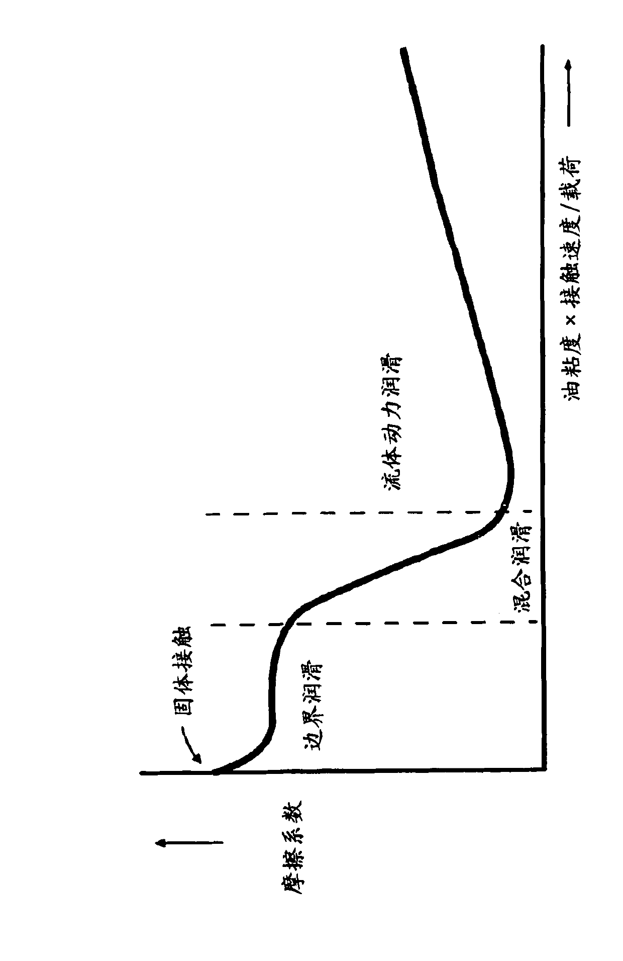
[0034] figure 1 The so-called Stribeck curve is shown. Piston ring and liner surfaces experience all three wear mechanisms as described by this curve, which relates (viscosity, load, velocity) to the coefficient of friction. The three mechanisms are boundary lubrication, mixed lubrication, and hydrodynamic lubrication. Hydrodynamic lubrication is the condition where surfaces are completely separated by an oil film. If the load is carried only partly by oil film pressure and partly by contact with asperities, the condition is called mixed lubrication. If the entire load is carried by the asperity and the only separation is a thin molecular oil film, then the condition is called boundary lubrication.

[0035] In large two-stroke diesel engines, boundary lubrication always exists to a lesser extent around top dead center (TDC), where the speed of the piston approaches zero. Where bore grinding is taking place, the amount of boundary lubrication will rise to the point where we...


PUM


Abstract

A method for detection of pre-scuffing events in a large multicylinder two-stroke diesel engine by recognizing the characteristic temperature fluctuations of pre-scuffing events. The temperature fluctuations are characterized by the time span between their peaks and the magnitude of the fluctuations. Automatic countermeasures may be initiated after detection of the pre-scuffing event. The countermeasures may automatically be ended.

Description

technical field [0001] The present invention relates to a method for detecting wear in a large two-stroke diesel engine, in particular to a method for detecting a pre-wear condition, a method for detecting a wear condition and a method for detecting a wear condition way to end. Background technique [0002] Malfunctions in the operation of large two-stroke diesel engines can result in reduced power and damage to cylinders and pistons. The power loss can be significant and in the event the engine has to be shut down, this can cause significant problems eg when using large two-stroke diesel engines as the main power source for ocean going vessels. [0003] Piston ring and cylinder liner surfaces experience such as Stribeck curve ( figure 1 ) for all three wear mechanisms described by the curve relates (viscosity, load, velocity) to the coefficient of friction. The three mechanisms are boundary lubrication, mixed lubrication, and hydrodynamic lubrication. Hydrodynamic lubri...

Claims


Application Information

Patent Timeline
IPC IPC(8): F02B77/08F02D35/02F02D41/22
CPCF02B77/089Y02T10/40F02D35/025F02D41/22G01M15/042F02B77/08F02D35/02
Inventor 亨里克·罗斯特德延森耶斯佩尔·魏斯福格延斯·巴格
Owner 曼能解决方案(曼能解决方案德国股份公司)分公司
Learn More