
Vehicle instrument system employing controller local area network bus

An instrument system and network bus technology, applied to vehicle components, simultaneously indicating the value of multiple variables, data exchange through path configuration, etc., can solve the problems of incompatibility of instruments, no data processing, and no scalability of functional design.

Inactive Publication Date: 2011-04-27
刘义胜
View PDF0 Cites 9 Cited by
  • Summary
  • Abstract
  • Description
  • Claims
  • Application Information

AI Technical Summary

Problems solved by technology

In addition, the wiring of sensing devices, data transmission issues, and system maintenance services for various systems on the vehicle are also relatively complicated. Traditional instrumentation devices are obviously not compatible with the new generation of electronic systems.
[0004] The main disadvantages of traditional vehicle instruments include that the instrument pointer rotates through the magnetic flux induction rotor to drive the pointer
Therefore, the external vibration of the vehicle will affect the rotation of the pointer, making its rotation accuracy limited by the magnetic flux value, which is not conducive to control and speed regulation, and the magnetic flux control is an analog control method, which cannot be applied to digital electronic systems.
In addition, due to the limitation of signal resolution, traditional vehicle instruments cannot be compatible with vehicles with vehicle communication network systems, nor can they receive data and analyze them, and have no data processing functions
Therefore, the function design of the traditional vehicle instrument has no expandability, and is limited to the manufacturer's factory settings, which cannot be modified to be used on other types of vehicles, which greatly limits the scalability and variability of the traditional vehicle instrument.

Method used


Image

  • Vehicle instrument system employing controller local area network bus
  • Vehicle instrument system employing controller local area network bus
  • Vehicle instrument system employing controller local area network bus

Examples


Embodiment Construction

[0063] Certain terms are used throughout the description and claims to refer to particular components. It should be understood by those skilled in the art that manufacturers may use different terms to refer to the same component. The specification and claims do not use the difference in name as a way to distinguish components, but use the difference in function of components as a basis for distinction. "Include" mentioned throughout the specification and claims is an open term, so it should be interpreted as "including but not limited to". Furthermore, the term "coupled" herein includes any direct and indirect means of electrical connection. Therefore, if it is described that a first device is coupled to a second device, it means that the first device can be directly connected to the second device, or indirectly connected to the second device through other devices or connection means. .

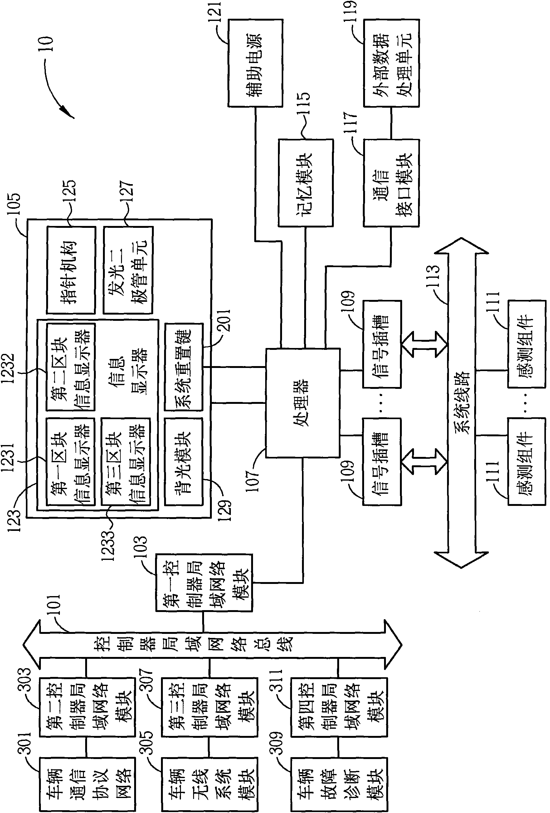
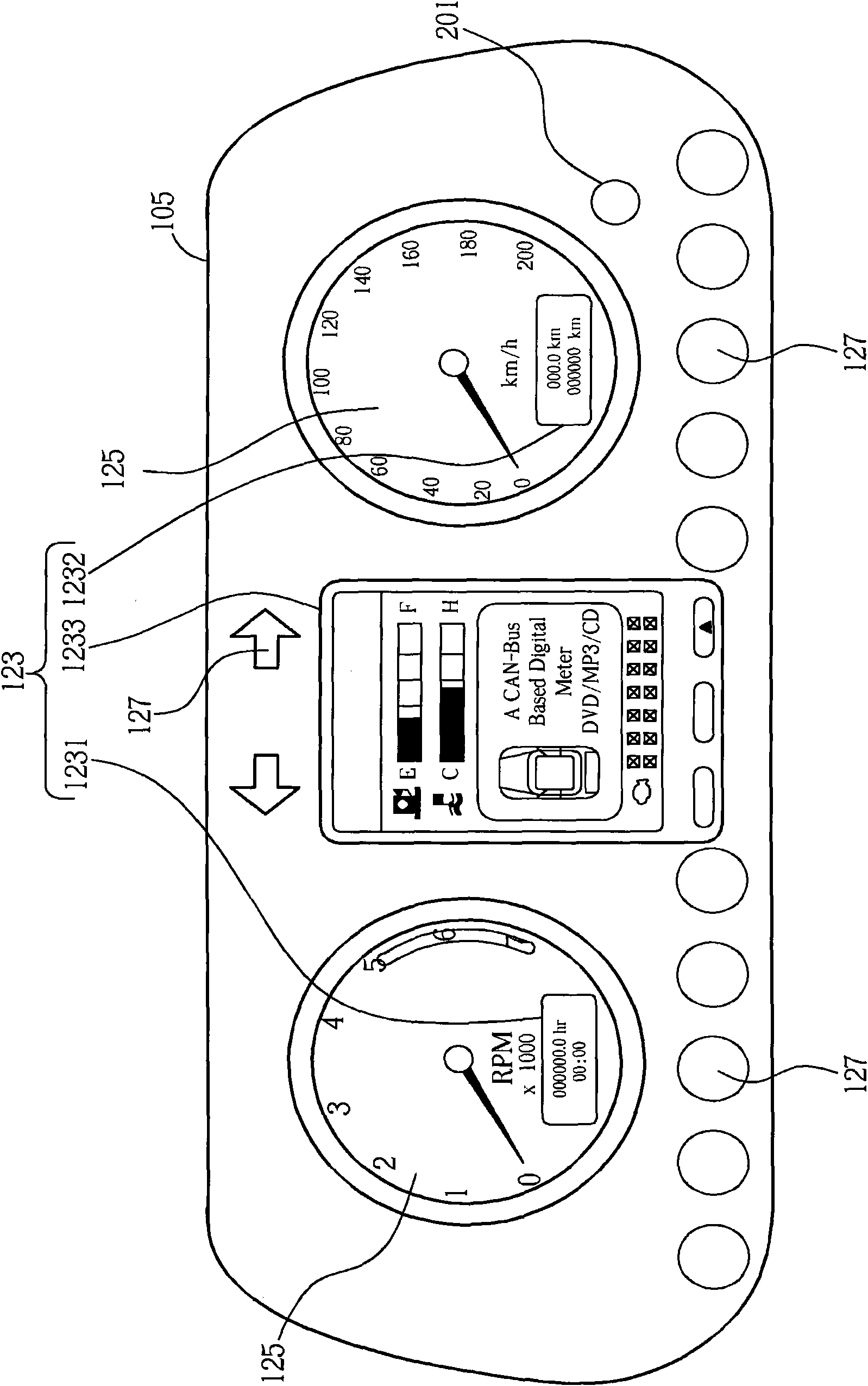
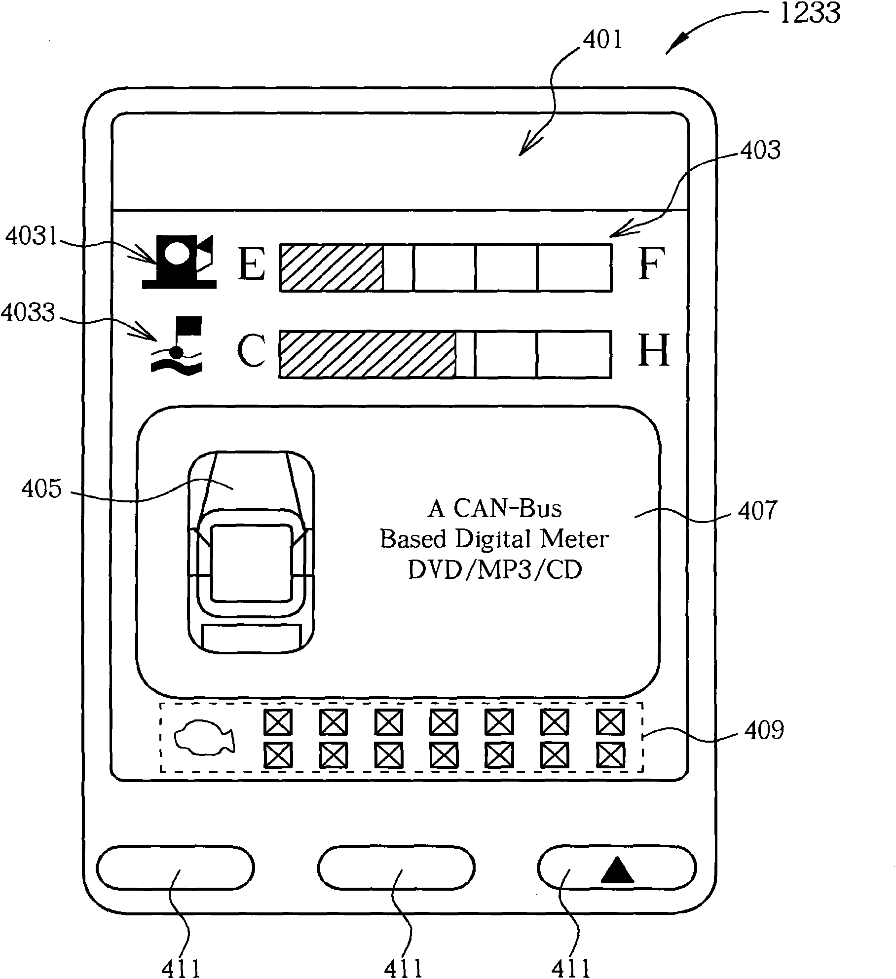
[0064] Please refer to figure 1 , figure 1 It is a schematic diagram of a vehicle in...


PUM


Abstract

The invention relates to a vehicle instrument system, which comprises a controller local area network bus for transmitting a controller local area network bus signal and a first controller local area network module coupled to the controller local area network bus. The first controller local area network module is used for receiving a controller local area network bus signal transmitted from the controller local area network bus and converting the controller local area network bus signal into an information signal. The vehicle instrument system further comprises an instrument panel and a processor which is coupled with the first controller local area network module and the instrument panel. The processor is used for receiving the information signal and controlling the instrument panel to display information corresponding to the information signal.

Description

technical field [0001] The invention relates to a vehicle instrument system, in particular to a vehicle instrument system using a controller local area network bus. Background technique [0002] Early vehicle instruments used the main shaft resistance of magnets and iron covers, and used non-magnetic good conductors (such as aluminum and copper) as pointer shaft rotors. The pointer shaft rotor, rotary force spring, totalizer, and transmission rotary gear are combined into an instrument head, so that the eddy current of the rotor interacts with the magnetic field of the permanent magnet, so that the rotor rotates to drive the pointer to rotate. Regardless of the information displayed by the pointer, light signal display or digital display device of the vehicle instrument, it receives the voltage signal or resistance signal of the general sensor. When the vehicle is running on a bumpy road, the instrument will shake or swing irregularly due to external vibration. In addition...

Claims


Application Information

Patent Timeline
IPC IPC(8): B60R16/023G01D7/04H04L12/28
Inventor 许源镛蔡汯峄吴建男曹旺昌
Owner 刘义胜
Learn More