Oxyopter type display device using holographic elements

A technology of vision and components, which is applied in the field of visual display devices, can solve the problems of affecting the display effect, not developing an ultra-thin display system, and inconvenient use, so as to achieve convenient application, compact structure, and reduced aberration and dispersion Effect

Active Publication Date: 2011-04-27
BEIJING INSTITUTE OF TECHNOLOGYGY
View PDF5 Cites 26 Cited by
  • Summary
  • Abstract
  • Description
  • Claims
  • Application Information

AI Technical Summary

Problems solved by technology

At present, general head-mounted displays and glasses-type displays cannot meet the technical requirements for adapting to the vision, and people with myopia and hyperopia have to wear correction glasses at the same t

Method used


Image

  • Oxyopter type display device using holographic elements
  • Oxyopter type display device using holographic elements
  • Oxyopter type display device using holographic elements

Examples


Embodiment Construction

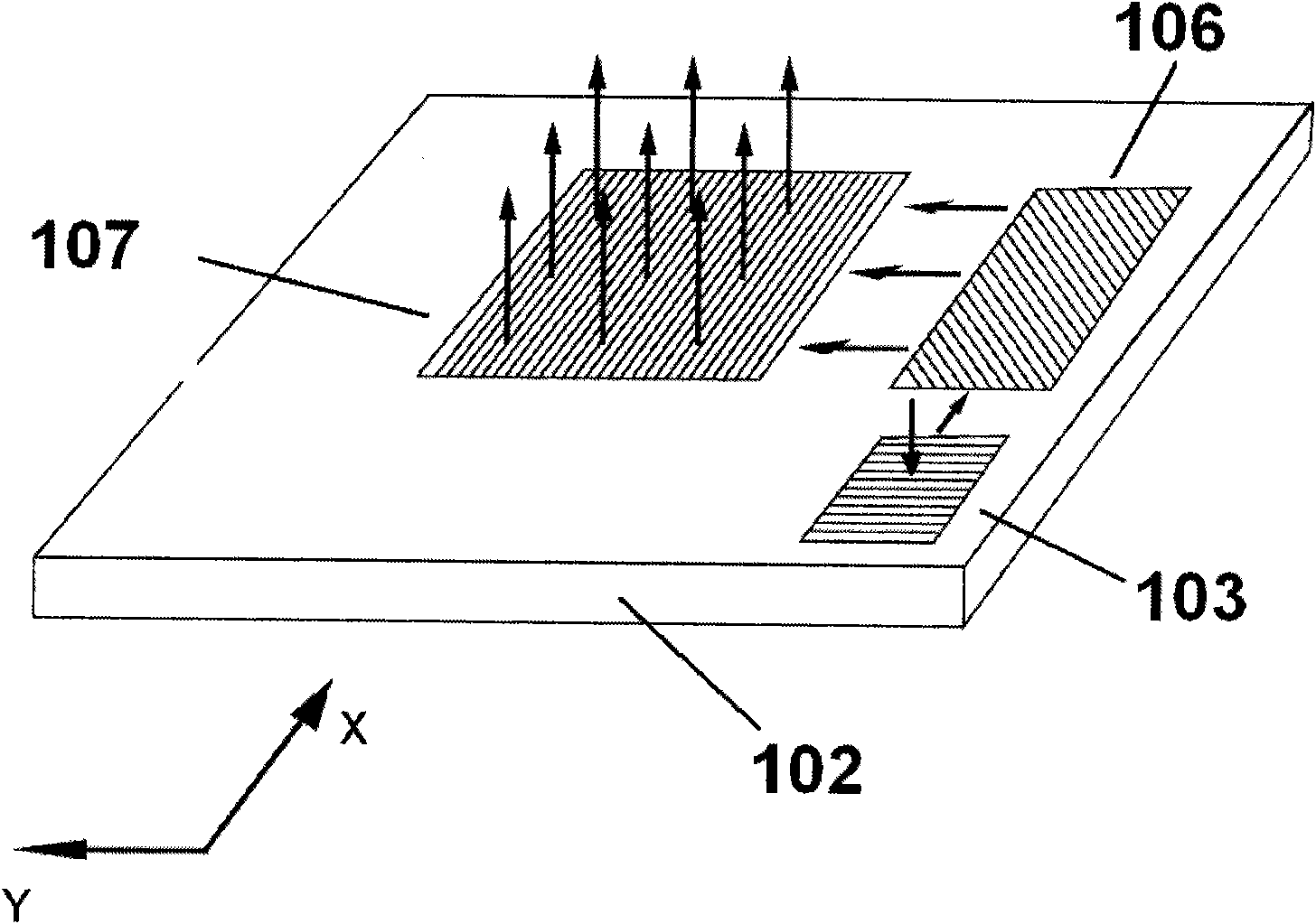
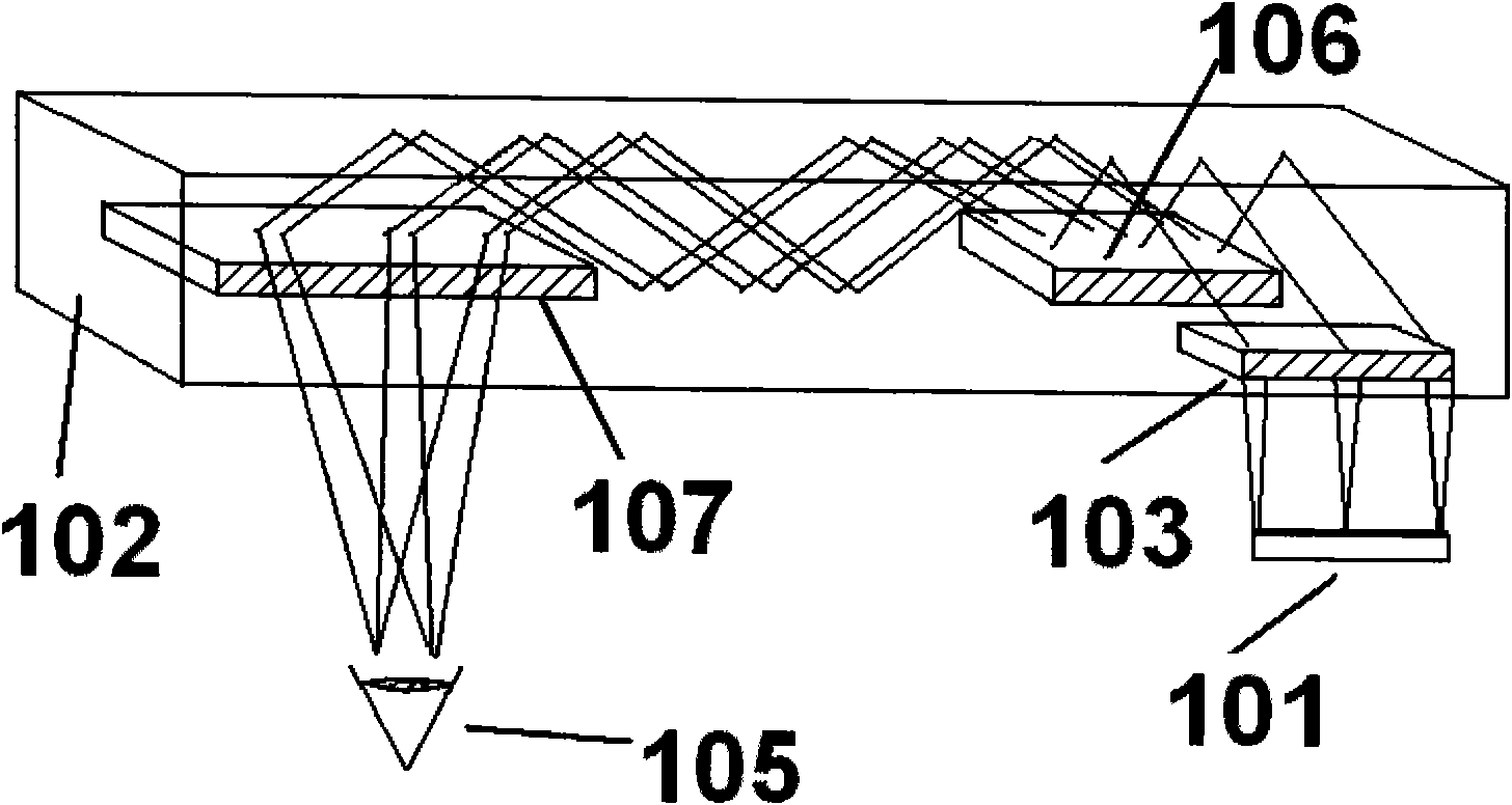
[0017] figure 2 is a three-dimensional view of the optical structure of the present invention, image 3 It is a schematic diagram of light transmission of the optical system of the present invention. The optical system of the present invention includes three holographic elements: holographic lens H1, holographic grating H2, and holographic lens H3. In the following content, in order to be unified with other symbols, different reference signs are used to distinguish the three elements, namely holographic lens 103 , a holographic grating 106 , and a holographic lens 107 . like figure 2 and 3 As shown, the illumination light of the holographic lens 103 comes from the image source element 101 facing it. The illumination light is directly irradiated on the holographic lens 103, and the holographic lens 103 acts as a collimating lens, which collimates the incident spherical wave into an angular spectrum plane wave (parallel light), and introduces the collimated light into an o...


PUM


Abstract

The invention relates to an optical system comprising three holographic elements, which can be used for a helmet-mounted display or a spectacle-mounted display. By using the optical display system, an image projected from an image source element can be subject to beam expansion by the three holographic elements and can be converted into divergent or convergent spherical waves for emission, thereby facilitating the wear of a user having a certain oxyopter. Because the display is realized by the holographic elements instead of lenses, the optical system provided by the invention is especially applicable to an ultra-thin display device, has the advantage of low manufacturing cost and can be customized according to user requirements.

Description

technical field [0001] The invention relates to a holographic optical device, in particular to a visual display device using three holographic optical elements (HOEs), including a helmet display or a glasses display. Background technique [0002] In the prior art, in order to watch a magnified virtual image with good image quality without using a complicated lens system, a similar figure 1 The virtual image viewing optical system shown is suitable for use on ultra-thin, easy-to-wear helmets, glasses-type displays, and the like. like figure 1 In the virtual image viewing optical system shown, the image light displayed on the image display device 11 is first incident on the optical waveguide 12 with the transmission holographic lens 13 inside. The incident image light is turned into parallel light by the transmission holographic lens 13, and the incident image light propagates in the optical waveguide 12 to satisfy the angle deflection of total reflection. A transmission ho...

Claims


Application Information

Patent Timeline
IPC IPC(8): G02B27/01G02B27/00G02B5/18
Inventor 王涌天潘奕捷刘娟刘冬梅史瑞谢敬辉
Owner BEIJING INSTITUTE OF TECHNOLOGYGY
Why Eureka
Try Eureka