Light irradiation apparatus

A technology for a light irradiation device and a bonding device, which is applied to lighting devices, lighting device parts, optics, etc., can solve the problems of low device reliability and low energy efficiency, and achieve high reliability, high energy efficiency, and realization The effect of manufacturing cost

Inactive Publication Date: 2011-04-27
USHIO DENKI KK
View PDF6 Cites 5 Cited by
  • Summary
  • Abstract
  • Description
  • Claims
  • Application Information

AI Technical Summary

Problems solved by technology

Therefore, there is a problem that the energy efficiency is low, and the movable parts in the shutter mechanism are prone to malfunction and the reliability of the device is low

Method used


Image

  • Light irradiation apparatus
  • Light irradiation apparatus
  • Light irradiation apparatus

Examples


Embodiment 1

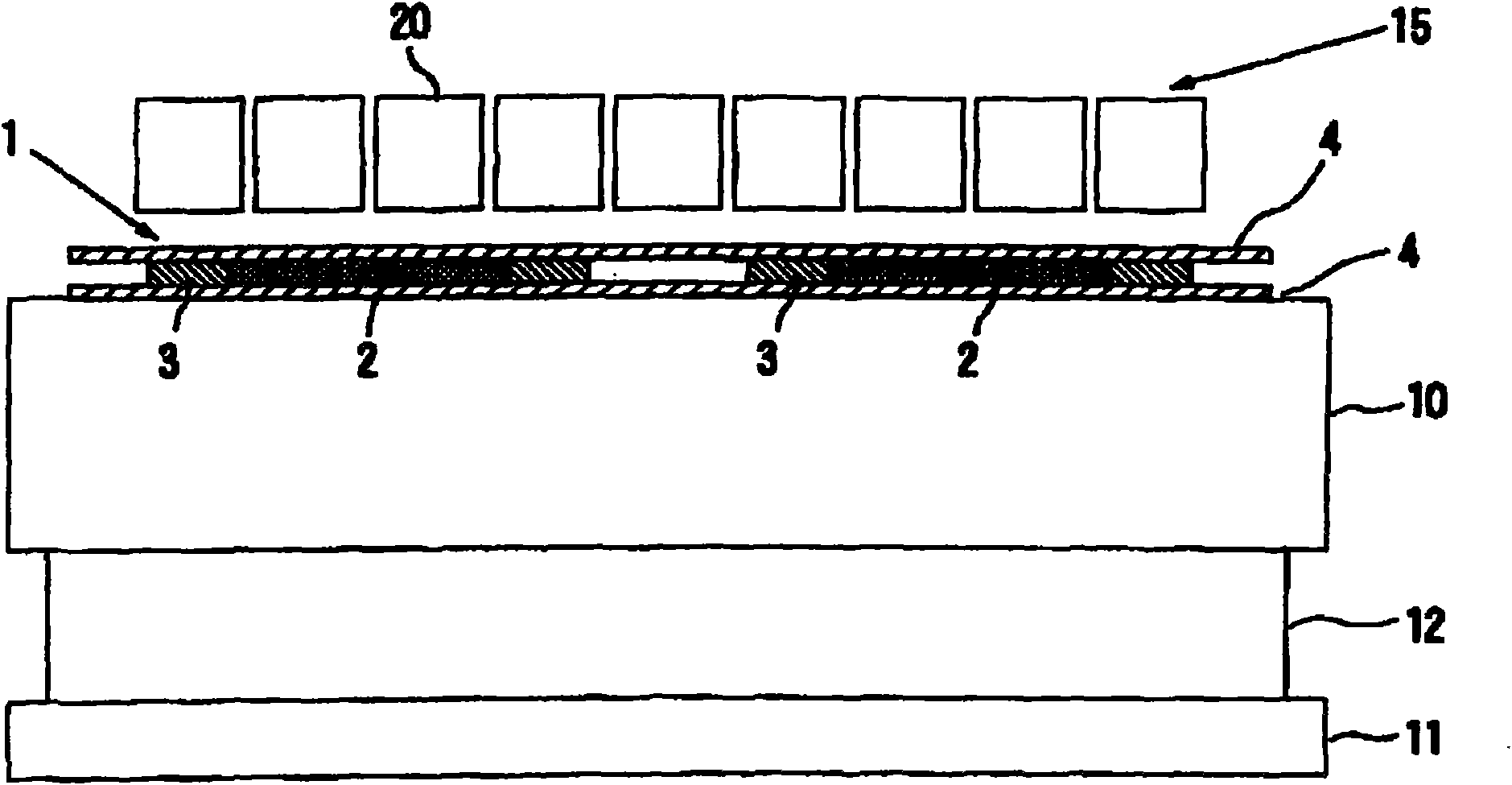
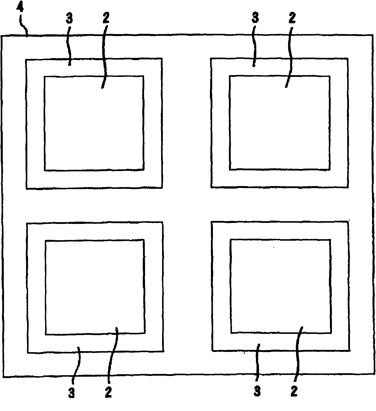
[0092] according to image 3 and Figure 4 With the structure shown, a light irradiation device was manufactured in which 130 light source segments were arranged vertically and horizontally. The specifications of the light source segment are as follows.

[0093] The vertical and horizontal dimensions of the substrate 21 are 50 mm×50 mm, and the overall length of the light guide member 26 is 45 mm.

[0094] The peak wavelength of the spectrum of the LED elements 25 is 385 nm, the full width at half maximum is ±5 nm, and nine light source segments are provided in one light source segment.

[0095] The optical filter 30 is a long-range optical filter having a dielectric multilayer film, and its cutoff wavelength is 380 nm.

[0096] The spectrum diagram of the light source section in the light irradiation device is shown in Figure 11 (a).


PUM

PropertyMeasurementUnit
strengthaaaaaaaaaa

Abstract

The present invention provides a light irradiation apparatus which is used by a jointing device of a display panel with a PSA mode, which does not cause polymerization of the polymerizable component contained in liquid crystal material and can irradiate light to a sealant layer with a higher light utilization efficiency for hardening. The light irradiation apparatus is used for the sealant layer which is composed of the following components: a polymerizable material layer which comprises the polymerizable component; photocurable sealant which surrounds the polymerizable material layer and has a sensitivity wavelength range that is provided at a wavelength side longer than the sensitivity wavelength range of the polymerizable component; and a jointing device of display panel, which is formed with a state between two light-penetrable substrates and irradiates light to the sealant layer thereby jointing the two light-penetrable substrates, wherein, the light irradiation apparatus comprises the following components: LED components; and a light filter which has a cutoff wavelength and shields the light at the short wavelength side, wherein the cutoff wavelength is at the wavelength side with wavelength that is shorter than a wavelength of a luminescence peak of the LED component and at the wavelength side with wavelength that is longer than a shortest wavelength of the spectrum of the LED component.

Description

technical field [0001] The present invention relates to a light irradiation device used as a light source in a display panel bonding device for bonding two light-transmitting substrates with a light-curing sealant in a manufacturing process of a display panel such as a liquid crystal panel. combine. Background technique [0002] In recent years, in liquid crystal panels, a PSA (Polymer Sustained Alignment) method or a PSVA method in which the alignment direction of liquid crystal molecules is restricted by a polymer structure has been developed for the purpose of improving the contrast and the response speed. , to replace the rib-like (リブ) structure formed inside the cell. [0003] In the manufacturing process of this PSA liquid crystal panel, a liquid crystal material containing a photopolymerizable component is injected into a cell, and a voltage is applied to the injected liquid crystal material while ultraviolet rays are irradiated to form a polymer structure in the cel...

Claims


Application Information

Patent Timeline
Patent Type & Authority Applications(China)
IPC IPC(8): G02F1/1339F21V9/00F21Y101/02
CPCG02F1/1303G02F1/1339
Inventor 羽田博成盐谷纱由矢野一晃
Owner USHIO DENKI KK
Why Eureka
Try Eureka