
Electrically erasable programmable read-only memory (EEPROM) circuit

A technology of memory circuits and memory unit circuits, which is applied in the field of memory circuits, can solve problems such as large leakage currents, and achieve the effects of reducing transient power consumption and leakage currents

Inactive Publication Date: 2011-04-27
天津南大强芯半导体芯片设计有限公司
View PDF7 Cites 0 Cited by
  • Summary
  • Abstract
  • Description
  • Claims
  • Application Information

AI Technical Summary

Problems solved by technology

cause a large leakage current when operating

Method used


Image

  • Electrically erasable programmable read-only memory (EEPROM) circuit
  • Electrically erasable programmable read-only memory (EEPROM) circuit
  • Electrically erasable programmable read-only memory (EEPROM) circuit

Examples


Embodiment

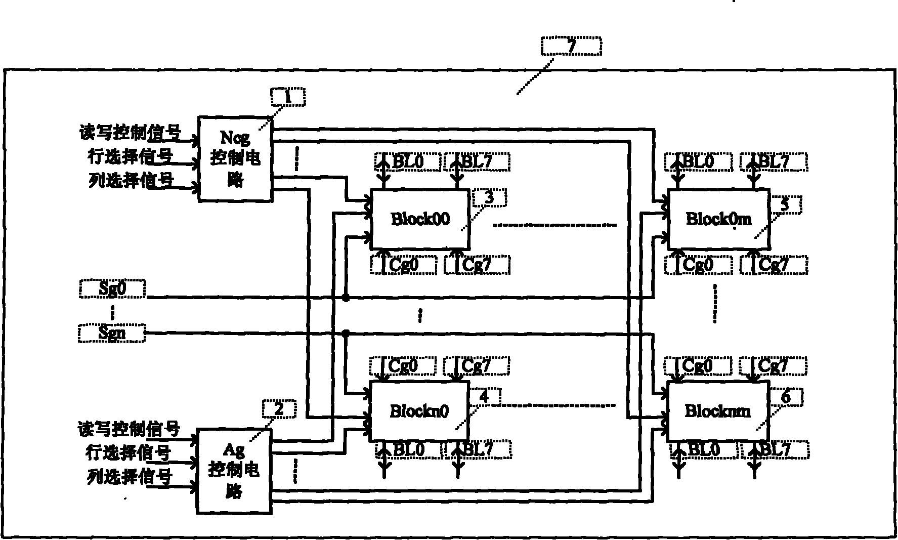
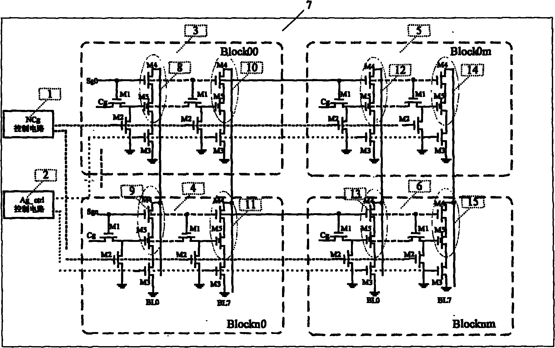
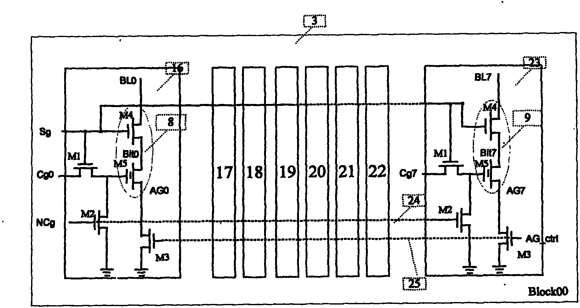
[0025] Embodiment: a kind of EEPROM memory circuit (see figure 1 , figure 2 ), which is characterized in that it includes a Cg terminal control circuit, an Ag terminal control circuit and a storage unit circuit; wherein the input end of the Cg terminal control circuit and the input end of the Ag terminal control circuit respectively receive collected digital signals, both The output terminal of is connected with the input terminal of the memory cell circuit.

[0026] The above-mentioned Cg terminal control circuit and Ag terminal control circuit (see Figure 4 ) consists of a two-input NOR gate, two inverters, a two-input AND gate and a two-input NAND gate, wherein the input terminals of said two-input NOR gate collect digital signals to be processed, and its output terminals are respectively connected to The input end of 1 inverter is connected with an input end of two-input NAND gate; the output end of said inverter connected with two-input NOR gate is connected with an in...


PUM


Abstract

The invention discloses an electrically erasable programmable read-only memory (EEPROM) circuit, which is characterized by comprising a Cg terminal control circuit, an Ag terminal control circuit and a memory cell circuit. The EEPROM circuit has the advantages of reducing the leakage current of a radio frequency identification tag (RFID TAG) storage array circuit and greatly reducing the transient power of the circuit.

Description

(1) Technical field: [0001] The invention relates to a memory circuit, especially an EEPROM memory circuit. (two) background technology: [0002] Such circuits are often used in storage circuits of passive RFID electronic tags. Storage arrays can save data information in the event of power failure. The storage information is read under power-on condition, and the storage information can be changed according to the external command. However, the circuit design is not fine, and no measures are taken for the leakage current generated by the transient state of the array. And since there is no power supply inside the tag, how to save transient energy consumption is the top priority. [0003] The existing circuit structure such as Figure 5 As shown, each block of the array controls the floating gate voltages of all memory cells through a control transistor, and the Ag terminals of all blocks are connected to be jointly controlled by the control circuit. Causes a large leakage...

Claims


Application Information

Patent Timeline
Patent Type & Authority Applications(China)
IPC IPC(8): G11C16/10
Inventor 张小兴程兆贤戴宇杰吕英杰
Owner 天津南大强芯半导体芯片设计有限公司
Learn More