
Heavy-calibre oil collection tube radiator for transformer

An oil collecting pipe and radiator technology, which is applied in the field of transformer accessories, can solve the problems of insufficient heat transfer oil, no energy saving, and increased power of the oil pump motor, so as to improve heat dissipation, avoid oil shortage, and reduce pressure loss.

Inactive Publication Date: 2011-04-27
CHANGSHU YOUBANG RADIATOR
View PDF4 Cites 9 Cited by
  • Summary
  • Abstract
  • Description
  • Claims
  • Application Information

AI Technical Summary

Problems solved by technology

[0003] For example, CN201185118Y (radiator of transformer), CN201185115Y (radiator with fan seat), CN201185117Y (fin radiator for transformer) and CN201229827Y of the oil collecting tube radiators for transformers in the prior art are all patented by the applicant. Although (radiating fin stepped radiators) have corresponding technical advantages, there are the following common technical problems: one is due to the constraints of traditional design concepts and design specifications, the design of the maximum diameter of the oil collecting pipe of the radiator It is 89mm (outer diameter), but through repeated experiments by the applicant, it has been found that the heat transfer oil pre-stored in the oil collection pipe is obviously insufficient before the radiator is cooled, so that the heat transfer oil in the oil collection pipe is not enough to fully Into each heat sink, the heat sink will be short of oil. On the other hand, the amount of oil in the oil return pipe is insufficient, and the amount of oil passing through the radiator in a unit time is small, and the heat dissipation effect is not ideal; The inner wall of the oil pipe and the oil return pipe has a large friction force, which leads to a large heat transfer (return) of the heat transfer oil itself; thirdly, the pressure loss of the heat transfer oil is large, which leads to an increase in the power of the oil pump motor, which is not energy-saving
[0004] The applicant believes that the above-mentioned problems are caused by the constraints of the traditional design ideas in the industry. stifles the motivation to innovate and excel

Method used


Image

  • Heavy-calibre oil collection tube radiator for transformer
  • Heavy-calibre oil collection tube radiator for transformer
  • Heavy-calibre oil collection tube radiator for transformer

Examples


Embodiment 1

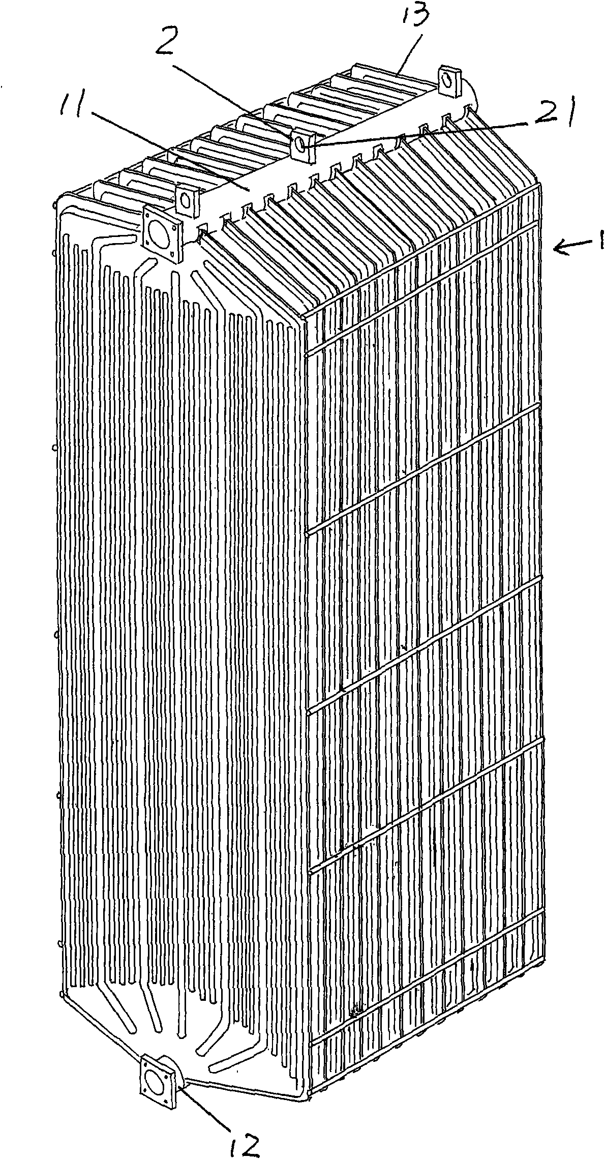
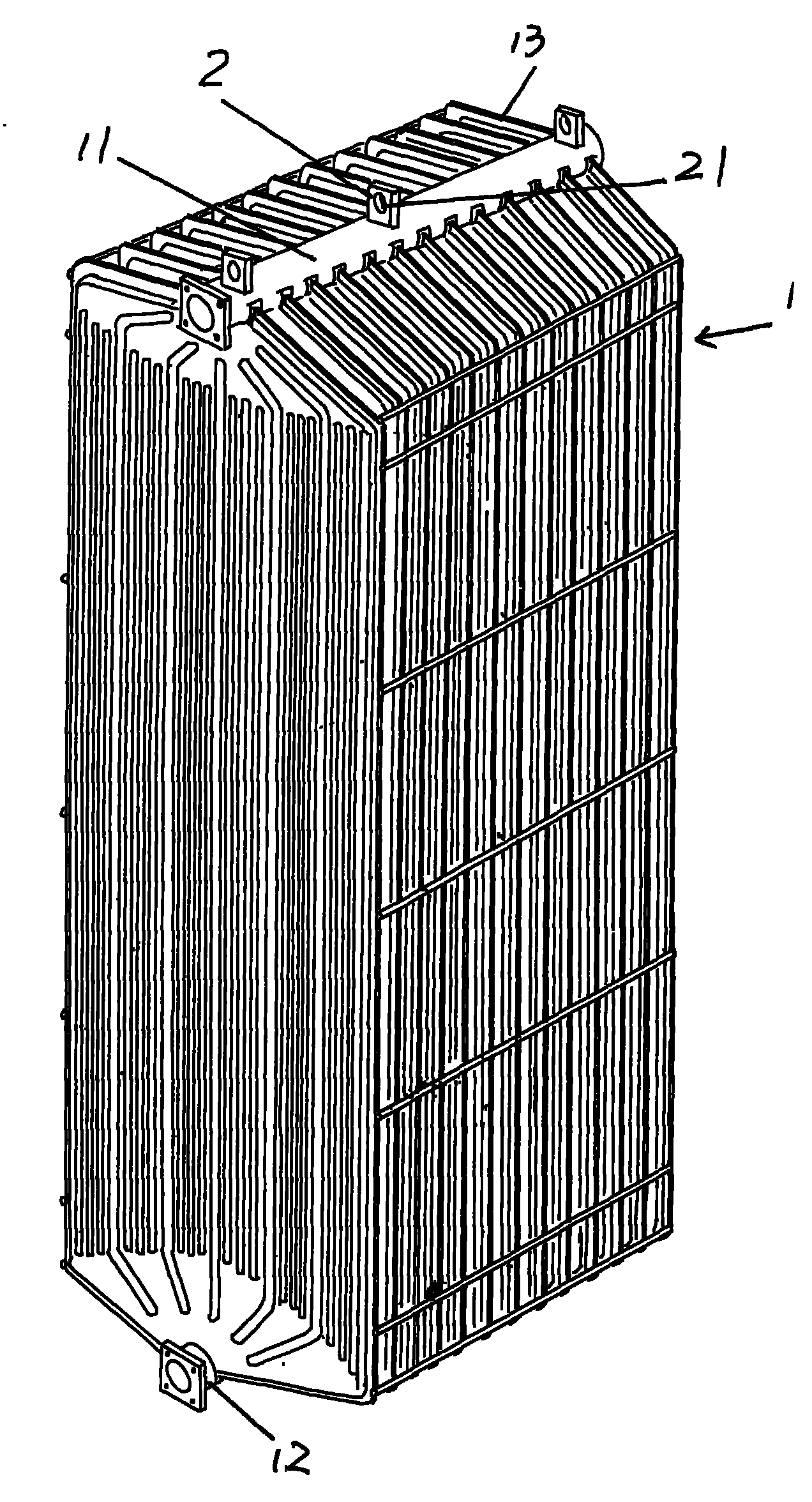
[0020] please see figure 1 , provides the radiator body 1, the radiator body 1 is made up of oil collecting pipe 11, oil return pipe 12 and a group of cooling fins 13, a group of cooling fins 13 are parallel to each other and keep the same distance between each other, each cooling fin 13 The upper end of each cooling fin 13 is connected with the oil collecting pipe 11 and the heat conducting oil cavity of each cooling fin 13 is communicated with the lumen of the oil collecting pipe 11; 12 lumens communicate. Lifting lugs 2 are fixed at intervals in the longitudinal direction of the aforementioned oil collecting pipe 11 and oil return pipe 12 , and hanging holes 21 are opened on the lifting lugs 2 . The preferred solution is: the lifting lugs 2 are arranged at intervals only in the length direction of the oil collecting pipe 11 , or the lifting lugs 2 are only arranged in the length direction of the oil return pipe 12 . It is self-evident that the effect of the lifting lug 2 ...

Embodiment 2

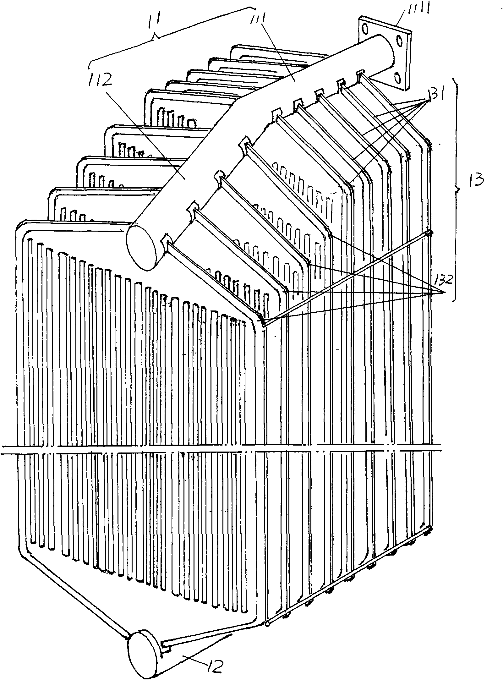
[0023] please see figure 2 , the given oil collecting pipe 11 is composed of a horizontal pipe section 111 and an inclined pipe section 112. Taking the current illustrated position as an example, the right end is a horizontal pipe section 111, while the left end is an inclined pipe section 112. The inclined pipe section 112 bends at one end of the horizontal pipe section 111. There is an oil inlet 1111 at the left end port of the horizontal pipe section 111. The hot oil from the transformer introduced by the oil inlet 1111 first enters the lumen of the horizontal pipe section 111 and then flows to the inclined pipe section 112. Since the oil collecting pipe 11 is formed by the horizontal pipe section 111 and the inclined pipe section 112, a group of cooling fins 13 are naturally formed of parallel cooling fins 131 and stepped cooling fins 132. One end of the oil return pipe 12 is connected and communicated, and the middle part of the upper and lower ends of the stepped coolin...


PUM

PropertyMeasurementUnit
diameteraaaaaaaaaa

Abstract

The invention discloses a heavy-calibre oil collection tube radiator for a transformer, belonging to the technical field of transformer accessories. The heavy-calibre oil collection tube radiator comprises a radiator body comprising an oil collection tube, an oil return tube and a group of cooling fins, wherein the cooling fins are gathered between the oil collection tube and the oil return tube and are matched with the oil collection tube and the oil return tube, and the diameter of the oil collection tube and the diameter of the oil return tube are respectively 114mm. By utilizing the heavy-calibre oil collection tube radiator provided by the invention, heat-conducting oil can fully enter each cooling fin conveniently, the phenomenon of oil lack is avoided, and the radiation effect is improved; the friction force between the heat-conducting oil and a tube wall is reduced, thus the operation heat of the heat-conducting oil is reduced; the diameter of the oil return tube is enlarged to increase the flow of oil, thus the amount of oil passing through the radiator within unit time is increased, and the radiation effect is more ideal; and after the diameter of the oil collection tube is enlarged, the pressure loss of oil is reduced so as to save the oil pump motor power.

Description

technical field [0001] The invention belongs to the technical field of transformer accessories, and in particular relates to a large-diameter oil-collecting pipe radiator for transformers. Background technique [0002] As known in the industry, the oil collector radiator is installed outside the large oil-immersed transformer, and forms a cooling circuit with the heat transfer oil inside the transformer through flange connection to cool the iron core of the transformer to ensure the normal operation of the transformer. [0003] For example, CN201185118Y (radiator of transformer), CN201185115Y (radiator with fan seat), CN201185117Y (fin radiator for transformer) and CN201229827Y of the oil collecting tube radiators for transformers in the prior art are all patented by the applicant. Although (radiating fin stepped radiators) have corresponding technical advantages, there are the following common technical problems: one is due to the constraints of traditional design concepts ...

Claims


Application Information

Patent Timeline
Patent Type & Authority Applications(China)
IPC IPC(8): H01F27/12
Inventor 王建忠
Owner CHANGSHU YOUBANG RADIATOR
Learn More