Three-phase current limiting device and method

A three-phase current, limiting device technology, applied in circuit devices, emergency protection circuit devices, emergency protection circuit devices for limiting overcurrent/overvoltage, etc., can solve the problem of insufficient utilization of resources and the effect of limiting short-circuit current Limited, complex circuit and other problems, to achieve the effect of flexible and convenient parameter index design, automatic short-circuit current limitation, and control circuit safety

Inactive Publication Date: 2013-07-17
SHANDONG UNIV
View PDF3 Cites 0 Cited by
  • Summary
  • Abstract
  • Description
  • Claims
  • Application Information

AI Technical Summary

Problems solved by technology

[0004] Invention patent No.: 2003101235398 "Superconducting Saturated Core Fault Current Limiter" proposes a current limiter that uses the saturation characteristics of the core of a magnetically saturated reactor to form a current limiter. This kind of fault current limiter requires superconducting materials and is expensive. The performance of superconducting materials is unstable, and the maintenance equipment is complicated
Invention patent No.: 2004100802846 "a fault current limiter" also proposes a current limiter that uses the saturation characteristics of the iron core of a magnetically saturated reactor to form a current limiter. The disadvantage of this current limiter is: to provide DC current to the DC coil The circuit is complex; the effect of limiting short-circuit current is limited; only the effect of limiting short-circuit current is not high cost performance, etc.
The three sets of single-phase settings work separately, and the management is more convenient; however, the comprehensive advantages of the joint work of the A, B, and C three-phase systems cannot be brought into play, and some of the mutually supporting resources of the A, B, and C three-phase systems cannot be fully utilized; The limitation of short-circuit current needs to be executed through the trigger command of the controller, and the reliability is not good enough

Method used


Image

  • Three-phase current limiting device and method

Examples


Embodiment Construction

[0028] The present invention will be further described below in conjunction with the accompanying drawings and embodiments.

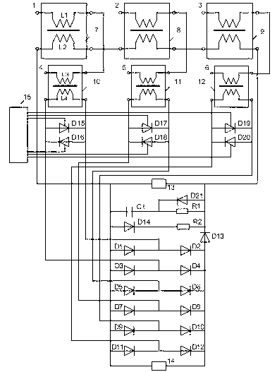
[0029] The structure and connection method of a three-phase current limiting device are as follows: figure 1 shown. it includes:

[0030] Phase A magnetically saturated reactor 7, B-phase magnetically saturated reactor 8 and C-phase magnetically saturated reactor 9; each magnetically saturated reactor has a closed-loop iron core, and each closed-loop iron core is respectively equipped with its own reactance coil L1, DC coil L2;

[0031] A-phase current transformer 10, B-phase current transformer 11 and C-phase current transformer 12; each current transformer has a closed-loop iron core respectively, and a primary coil L3 and a secondary coil L4 are respectively installed on each closed-loop iron core;

[0032] Three pairs of anti-parallel thyristors, three pairs of anti-parallel thyristors are respectively connected in parallel with the secondary coi...


PUM


Abstract

A device and a method for limiting three-phase current are disclosed. The device includes three magnetically saturated reactors (7, 8, 9), each provided with a reactive coil (L1) and a direct-current coil (L2) respectively; three current transformers (10, 11, 12), each provided with a primary coil (L3) and a secondary coil (L4) respectively; three pairs of anti-parallel thyristors (D15, D16, D17, D18, D19, D20), connected in parallel with the secondary coil (L4) of each current transformer respectively; a three-phase bridge rectification circuit; and a control circuit. Wherein, the reactive coils (L1) of the magnetically saturated reactors are connected in series with the primary coils (L3) of the current transformers; the remaining terminals (1, 2, 3) of the reactive coils (L1) act as input terminals of phase A, phase B and phase C of the device; and the remaining terminals (4, 5, 6) of the primary coils (L3) of the current transformers act as output terminals of phase A, phase B and phase C of the device. The secondary coils (L4) of the current transformers act as inputs of the three-phase bridge rectification circuit, and the outputs of the three-phase bridge rectification circuit, after they are connected in series with a forward diode (D13), are connected in series with the direct-current coils (L2) of the magnetically saturated reactors, so as to form a closed direct-current circuit. The outputs of the control circuit determine breakover or cut-off of the three pairs of anti-parallel thyristors respectively.

Description

technical field [0001] The invention relates to the technical field of power transmission and transformation in power systems, in particular to a three-phase current limiting device and method. Background technique [0002] With the continuous development of the power system and the continuous increase of power generation capacity, the short circuit current caused by the short circuit of the power system is very large. The short circuit current caused by the short circuit in the power system is very harmful to the power system. When a short circuit occurs in the power system, the relay protection device issues a trip command to trip the circuit breaker and cut off the short circuit current. The ability of the circuit breaker to cut off the short-circuit current is limited. When the short-circuit current exceeds the maximum cut-off current value of the circuit breaker, the circuit breaker cannot cut off the short-circuit current. Therefore, reducing the short-circuit curren...

Claims


Application Information

Patent Timeline
Patent Type & Authority Patents(China)
IPC IPC(8): H02H9/02
CPCH02H9/021
Inventor 李晓明
Owner SHANDONG UNIV
Why Eureka
Try Eureka