Method of detection of welding workpiece position using movable electrode

一种工件位置、检测方法的技术,应用在焊接设备、电阻焊设备、制造工具等方向,能够解决易成为不稳定、焊接工件变形、难可动电极与焊接工件接触时刻等问题

Active Publication Date: 2011-05-04
FANUC LTD
View PDF10 Cites 24 Cited by
  • Summary
  • Abstract
  • Description
  • Claims
  • Application Information

AI Technical Summary

Problems solved by technology

However, since it takes time to set the thickness of the workpiece to be welded, there is a problem that it is difficult to individually set the thickness of hundreds of dotting positions in actual welding work.
Moreover, when setting the thickness of the welding workpiece at each point position according to the value on the design data of the welding workpiece, due to the influence of gaps between the welding workpieces or individual differences in the welding workpieces, sometimes the opposing electrodes do not contact the welding workpiece, or face each other. Excessive pressing of the electrode against the welded workpiece deforms the welded workpiece and in the worst case plastically deforms the welded workpiece or damages the spot welding torch
Therefore, there is also the following problem: in order to prevent the deformation of the welding workpiece and the damage of the spot welding gun, the thickness of the welding workpiece must be measured in advance at all the spot positions on the welding workpiece before the thickness of the welding workpiece is set.
However, when the movable electrode is driven by the servo motor to move, due to the mechanical resistance existing in the spot welding gun (for example, internal friction of the driving part, elastic deformation of the conductive part connecting the movable electrode to the welding transformer, etc.), Fluctuations or fluctuations occur in the current or torque of the servo motor that drives the movable electrode, and it is easy to become an unstable state
Therefore, the increase in the current or torque of the servo motor generated when the movable electrode is in contact with the welding workpiece is hidden in the fluctuation or variation caused by the mechanical resistance of the spot welding gun, and it is difficult to accurately determine the contact timing of the movable electrode and the welding workpiece. Causes false detection of contact between the movable electrode and the welding workpiece

Method used


Image

  • Method of detection of welding workpiece position using movable electrode
  • Method of detection of welding workpiece position using movable electrode
  • Method of detection of welding workpiece position using movable electrode

Examples


Embodiment A1

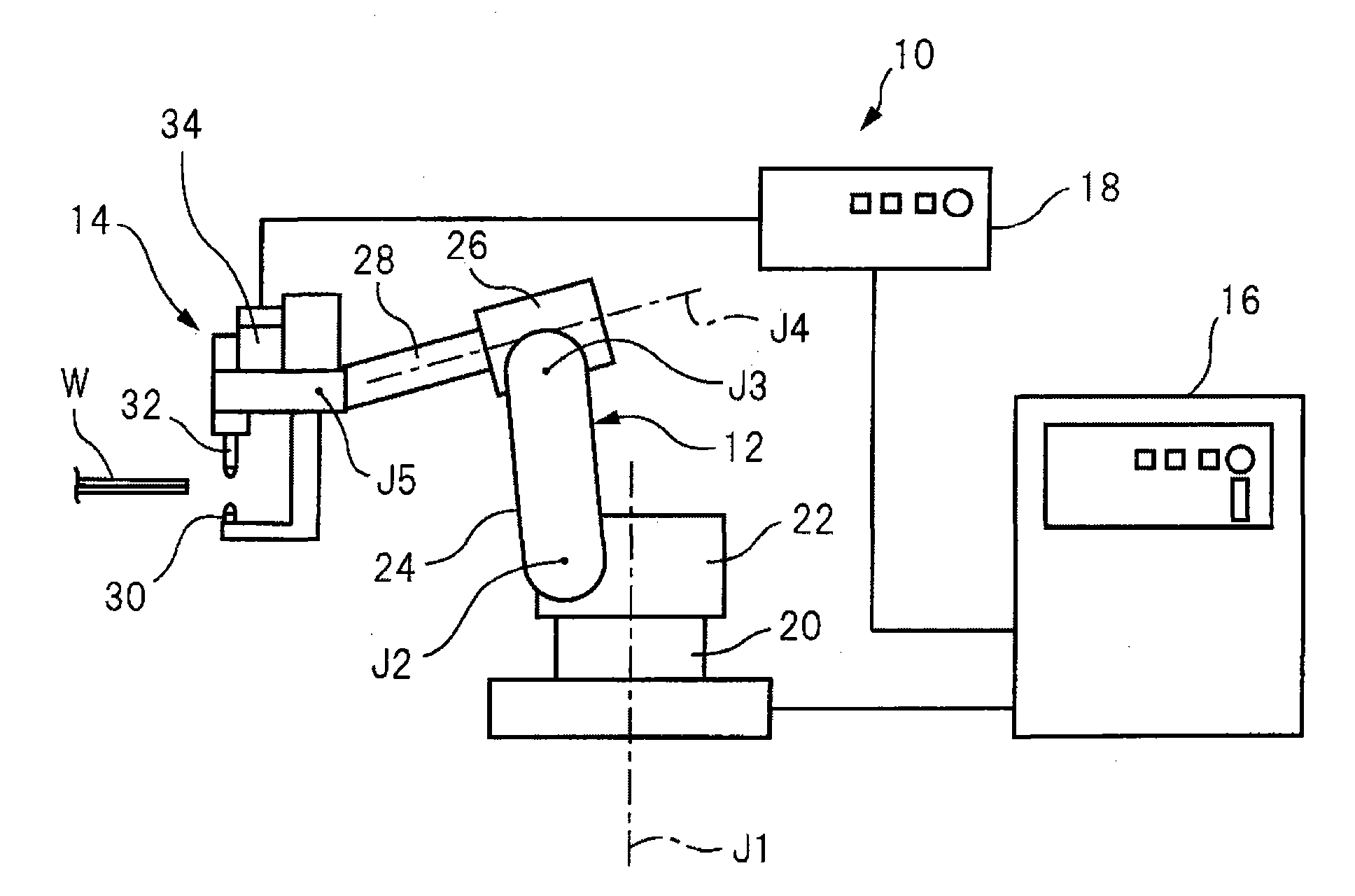
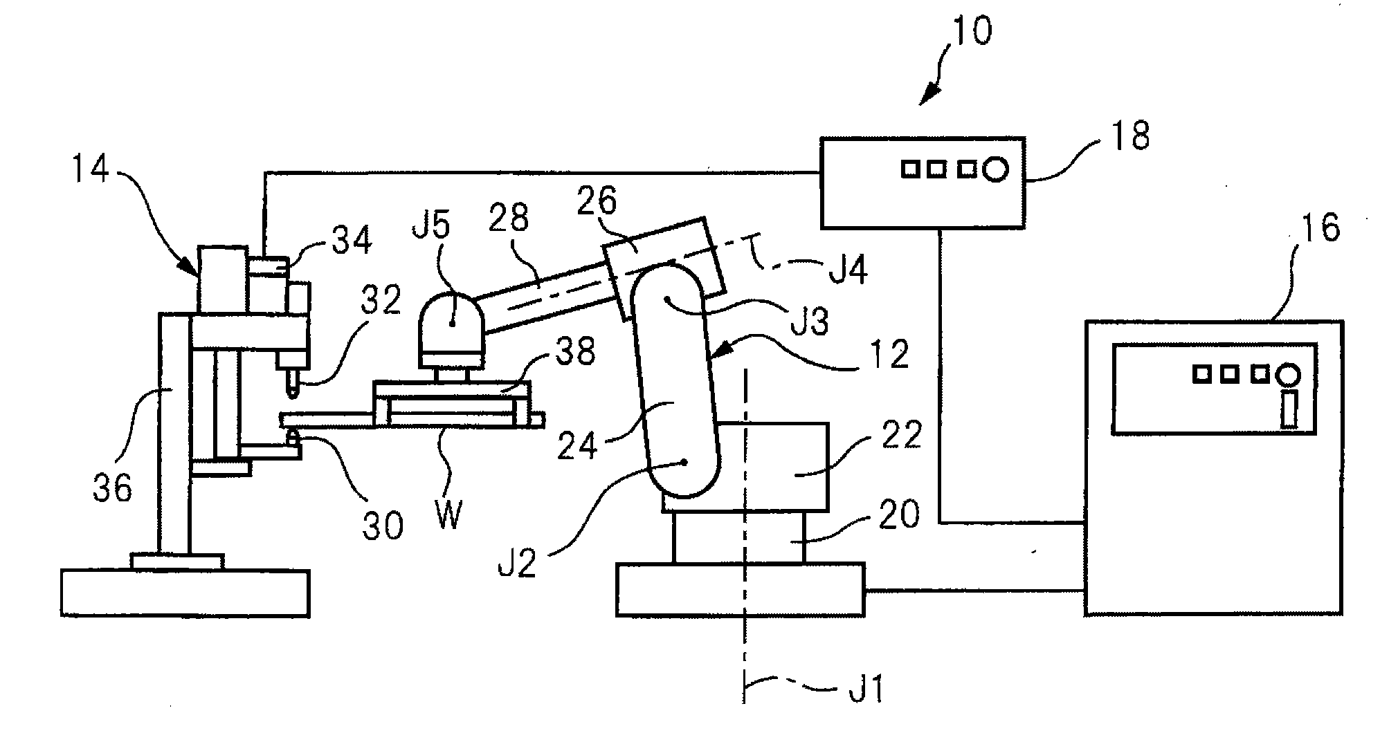
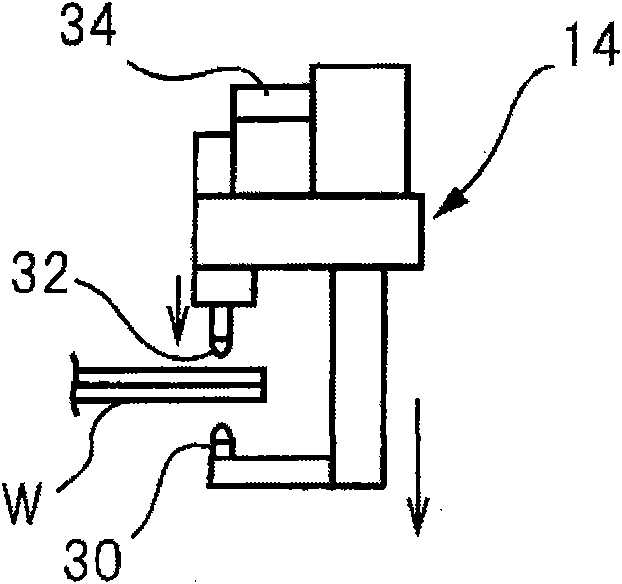
[0121] refer to Figure 6 The A1st embodiment of the welding workpiece position detection method of the present invention will be described. In the A1 embodiment, in figure 1 In the spot welding system 10 shown, the speed Vg at which the servo motor 34 drives the movable electrode 30 is set to 0, and the spot welding gun 14 is held by the articulated robot 12 in a state where the movable electrode 30 is stationary relative to the counter electrode 32 , making it relatively move at a speed Vr relative to the welding workpiece W fixed on the workpiece fixing table (not shown). In addition, a torque limit is set for the servo motor 34 for driving the movable electrode 30, and the torque does not increase above a constant value. In order to suppress the deformation of the welding workpiece W caused by the pressing of the movable electrode 30, it is desirable to set the torque limit to a value as low as possible.

[0122] In the present embodiment, at first, the workpiece W to b...

Embodiment A2

[0137] The A2 embodiment differs from the A1 embodiment in that figure 1 In the shown spot welding system 10, the speed Vg at which the movable electrode 30 is driven by the servo motor 34 is not 0, and while the movable electrode 30 is moved by the servo motor 34, the spot welding gun 14 is held by the articulated robot 12, so that The movable electrode 30 moves relative to the welding workpiece W fixed on the workpiece fixing table (not shown) at the speed Vr, and the rest is the same as that of the A1st embodiment. Therefore, here, different parts will be mainly described, and the description of the same parts will be omitted.

[0138] In the A1 embodiment, there is an advantage that, since the speed Vg at which the servo motor 34 drives the movable electrode 30 is set to 0, and the movable electrode 30 is kept stationary relative to the counter electrode 32, there is almost no occurrence of a fault caused by the movable electrode 30. Fluctuation of the current or torque o...

Embodiment A3

[0158] refer to Figure 11 A third embodiment of the welding workpiece position detection method of the present invention will be described. In the A3 embodiment, in figure 1 In the spot welding system 10 shown, the speed Vg at which the servo motor 34 drives the movable electrode is set to 0, and the spot welding gun 14 is held by the articulated robot 12 in a state where the movable electrode 30 is stationary relative to the counter electrode 32, The spot welding gun 14 is relatively moved at a speed Vr with respect to a welding workpiece W fixed on a workpiece fixing table (not shown). In addition, a torque limit is set for the servo motor 34 for driving the movable electrode 30, and the torque does not increase when it exceeds a constant value or more. In order to suppress the deformation of the welding workpiece W caused by the pressing of the movable electrode 30, it is desirable to set the torque limit to a value as low as possible.

[0159] In the present embodiment...


PUM


Abstract

A method of detection of a welding workpiece position using a movable electrode, in a spot welding system, a welding workpiece and a spot welding gun are moved relatively by a multi-articulated robot, such that the movable electrode is closed to the welding workpiece or the movable electrode is separated from the welding workpiece, simultaneously, a current or torque of a servo motor is monitored, and a surface position of the welding workpiece is detected from the position of the movable electrode and the position of the multiarticulated robot when the trend of the current or torque changes.The spot welding system comprises: the spot welding gun having the movalbe electrode driven by the servo motor and a counter electrode arranged facing the movable electrode, and the multiarticulated robot for holding one of the welding workpiece and the spot welding gun. Thereby, the precision of detection of the surface position of the welding workpiece by the movable electrode in the spot welding system can now be improved without lengthening the time required for detection of the surface position of the welding workpiece.

Description

technical field [0001] The invention relates to a method for detecting the position of a welding workpiece, which uses a multi-joint robot to move the welding workpiece and the spot welding gun relatively, and clamps the welding workpiece between the opposing movable electrode and the opposing electrode of the spot welding gun to perform the welding of the workpiece In the spot welding system of spot welding, a movable electrode is used to detect the surface position of the welding workpiece. Background technique [0002] The spot welding system has: a spot welding gun having a movable electrode driven by a servo motor and a counter electrode disposed facing it; After the relative movement, the movable electrode and the opposite electrode of the spot welding gun are closed towards the preset dotting position on the welding workpiece, and the welding workpiece is clamped between the movable electrode and the opposing electrode of the spot welding gun. In this state, the A vo...

Claims


Application Information

Patent Timeline
Patent Type & Authority Applications(China)
IPC IPC(8): B23K11/11B25J13/08
CPCB23K11/115
Inventor 高桥广光青木俊道西村昭典
Owner FANUC LTD
Why Eureka
Try Eureka