Array induction logging coil system for measuring formation resistivity

A technology of formation resistivity and array induction, which is applied in the fields of electrical/magnetic detection for logging records, wellbore/well components, earthwork drilling and production, etc. It can solve problems that are difficult to obtain, complicated in circuit design, difficult in processing, etc. question

Active Publication Date: 2011-05-04
BC P INC CHINA NAT PETROLEUM CORP +1
View PDF7 Cites 33 Cited by
  • Summary
  • Abstract
  • Description
  • Claims
  • Application Information

AI Technical Summary

Problems solved by technology

[0004] In Halliburton's array induction logging tool HRAI, the spacing of the subarrays does not have a logarithmic equidistant relationship, and there is a lot of repeated information between the subarrays; the shortest subarray (18in.) is too long, and its detection depth (0.44m ) is much larger than the detection depth of 0.25m to be synthesized, it is difficult to obtain this curve in actual signal synthesis
The high-frequency working range of the eldest sub-array is 1.9S / m, which is too narrow to be suitable for dual-frequency skin effect correction
Its improved ACRt has only 6 sub-arrays. Once sub-array 1 is seriously affected by the wellbore, it will be difficult to handle. The frequencies are 12kHz, 36kHz and 72kHz, which are not the same multiple of each other, and the circuit design is complicated

Method used


Image

  • Array induction logging coil system for measuring formation resistivity
  • Array induction logging coil system for measuring formation resistivity
  • Array induction logging coil system for measuring formation resistivity

Examples


Embodiment 1

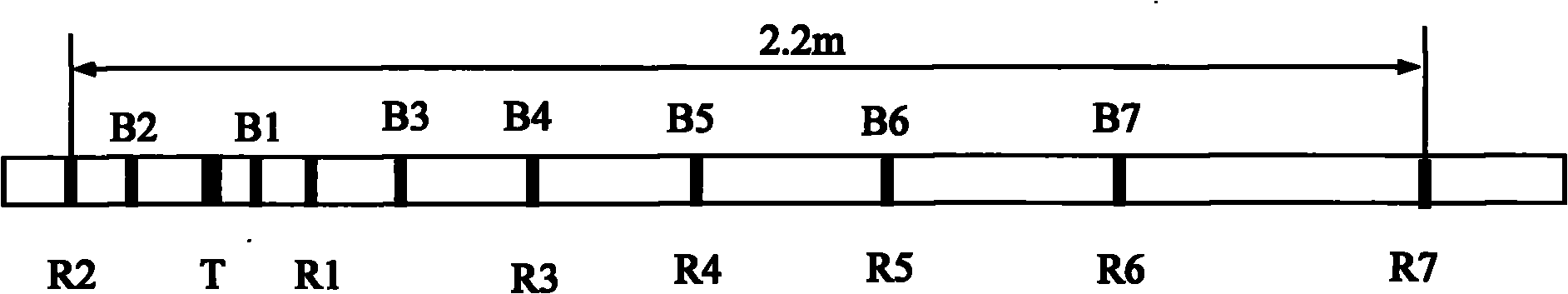
[0060] figure 1 It is a schematic diagram of the first arrangement of the coil system in the present invention.

[0061] The multi-array multi-frequency induction coil system structure is composed of 1 transmitting coil and 7 independent 2-coil sub-arrays. In the figure, T represents the transmitting coil; R1, R2, R3, R4, R5, R6 and R7 represent 7 main receiving coils. Coils; B1, B2, B3, B4, B5, B6 and B7 represent 7 shielded coils. The second short sub-array is placed on one side alone, and the remaining 6 sub-arrays are on the other side. The shielding coils of sub-arrays R4, R5, R6 and R7 coincide with the main receiving coils of sub-arrays R3, R4, R5 and R6. This method can reduce the influence of the coil bobbin on other sub-arrays due to the cancellation of the direct-coupled signal during assembly.

Embodiment 2

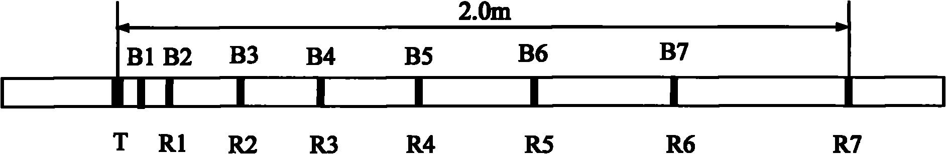
[0063] figure 2 It is a schematic diagram of the second arrangement of the coil system in the present invention. All subarrays are arranged on one side, and the shielding coils of subarrays R1, R2, R3, R4, R5, R6, and R7 coincide with the main receiving coils of subarrays R1, R2, R3, R4, R5, and R6. This method shortens the length by 0.2m compared to the first method.

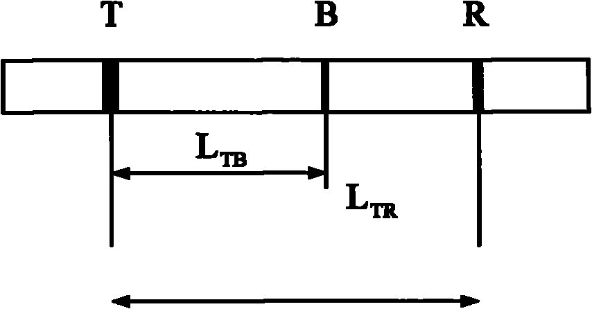
[0064] image 3 for correspondence figure 1 and figure 2 Schematic diagram of the 3-coil system subarray structure. image 3 is corresponding figure 1 and figure 2 Schematic of the 3-coil system subarray. The shielding coil B is arranged between the transmitting coil and the main receiving coil to cancel the direct coupling signal between the transmitting and the main receiving, and its number of turns and spacing are designed to meet the requirements of the present invention.

[0065] Fig. 4 is a diagram of radial differential and integral geometric factors corresponding to the multi-array coil syst...


PUM


Abstract

The invention relates to an array induction logging coil system for measuring the formation resistivity. The coil system consists of a transmitting coil and 7 sets of double-receiving coils which consist of a plurality of screening coils and a plurality of main receiving coils, wherein the transmitting coil and each set of the double-receiving coils form a sub array, all 15 coils are wound on a non-conductive frame, the screening coils are connected with the main receiving coils in series, however, the winding directions of the screening coils and the main receiving coils are opposite, the set of the position of the main receiving coils considers the radial investigation depth, the lengthways resolution ratio and the signal focusing and synthesizing treatment requirement, the screening coils are arranged between the transmitting coil and the main receiving coils, the position and the number of the screening coils meet the condition of offsetting direct coupled signals, change the radial investigation depth and the lengthways resolution ratio, and meet the condition that the signal to noise ratio is 2-4; the other screening coils except the first sub array coil in the 7 sub array coils are overlapped with the center positions of the main receiving coils of the former sub array; and the investigation range of the resistivity is wide, so that the coil system can measure the formation resistivity more accurately.

Description

technical field [0001] The invention relates to an array induction logging coil system for detecting formation resistivity around an open hole, which belongs to geophysical logging technology. Background technique [0002] Among the current logging tools, Schlumberger’s array induction logging tool AIT, when arranged according to the spacing of the receiving coils from short to long, each spacing no longer has a logarithmic equidistant relationship, and each sub-array has a relatively Multiple radial and longitudinal repetitions; 7 sub-array detection depths include 3 composite detection depths (10, 20 and 30in.), but 60in. and 90in. are between the seventh and eighth sub-arrays , once the eighth sub-array is inaccurate, the detection depths of 60in. and 90in. are unreliable; the working range of the real part signal of the longest subarray 8 is too small (less than 3.1S / m), the imaginary part signal must be used, and the real part must be used at the same time And the imag...

Claims


Application Information

Patent Timeline
Patent Type & Authority Applications(China)
IPC IPC(8): E21B49/00G01V3/28
Inventor 李长文仵杰周军陈涛李梦春
Owner BC P INC CHINA NAT PETROLEUM CORP
Why Eureka
Try Eureka