Magnetic liquid damping device

A technology of magnetic liquid and vibration damping device, applied in the direction of magnetic spring, spring/shock absorber, spring, etc., can solve the problems of weak frictional energy dissipation capacity, weak binding magnetic liquid, weak magnetic field inside the tube, etc., to increase friction Area, good vibration damping effect, and large external surface area

Inactive Publication Date: 2011-05-04
BEIJING JIAOTONG UNIV
View PDF5 Cites 49 Cited by
  • Summary
  • Abstract
  • Description
  • Claims
  • Application Information

AI Technical Summary

Problems solved by technology

The magnetic field inside the tube is also weak, and the ability to bind the magnetic liquid is weak. The magn

Method used


Image

  • Magnetic liquid damping device
  • Magnetic liquid damping device
  • Magnetic liquid damping device

Examples


Embodiment approach 1

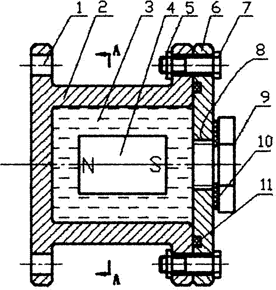
[0020] A magnetic liquid vibration damping device, which includes a non-magnetic shell 2, a magnetic liquid 3, a permanent magnet 4, a nut 5, an end cover 6, a bolt 7, a screw 9, a gasket 10 and an O-ring 11; the above parts the connection between:

[0021] Put the permanent magnet 4 into the cavity of the non-magnetic shell 2, and fix the end cover 6 with the O-ring 11 on one end of the non-magnetic shell 2 with the bolt 7 and the nut 5;

[0022] Fill the cavity of the non-magnetic shell 2 with magnetic liquid 3 through the threaded hole 8, and seal it with screws 9 and gaskets 10.

[0023] The inner diameter of the cavity of the non-magnetic shell 2 is 30 mm, and the diameter of the permanent magnet 4 is 13.5 mm.

[0024] The length of the non-magnetic shell 2 is 60 mm, and the length of the permanent magnet 4 is 18 mm.

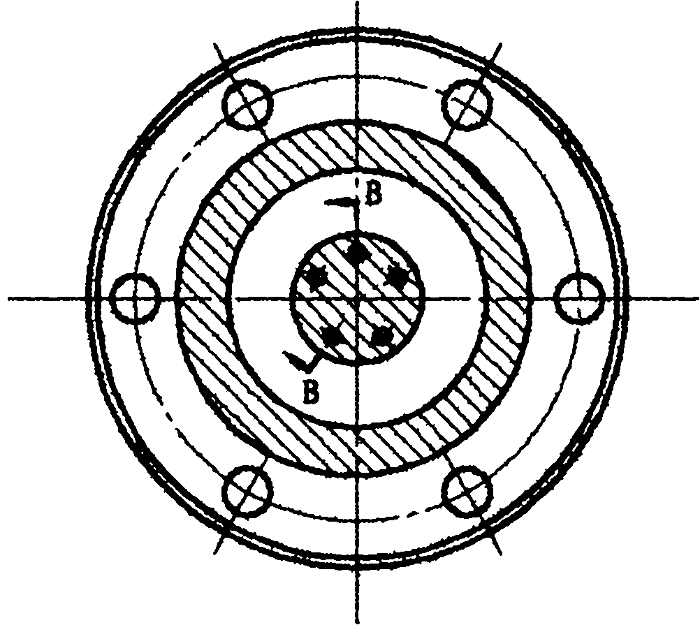
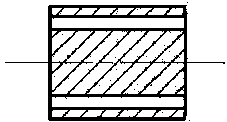
[0025] The permanent magnet 4 is a cylinder, and four through holes are evenly distributed axially in the cylinder. The diameter of each through hole is...

Embodiment approach 2

[0031] The difference between Embodiment 2 and Embodiment 1:

[0032] The inner diameter of the cavity of the non-magnetic shell 2 is 30 mm, and the diameter of the permanent magnet 4 is 24 mm.

[0033] The length of the cavity of the non-magnetic shell 2 is 60 mm, and the length of the permanent magnet 4 is 45 mm.

[0034] The permanent magnet 4 is a cylinder, and 6 through holes are evenly distributed axially in the cylinder. The diameter of each through hole is 3.6mm.

[0035] The magnetic fluid 3 is a water-based magnetic fluid.

Embodiment approach 3

[0037] The difference between Embodiment 3 and Embodiment 1:

[0038] The inner diameter of the cavity of the non-magnetic shell 2 is 40 mm, and the diameter of the permanent magnet 4 is 24 mm.

[0039] The length of the cavity of the non-magnetic shell 2 is 60 mm, and the length of the permanent magnet 4 is 36 mm.

[0040] The permanent magnet 4 is a cylinder, and 8 through holes are evenly distributed axially in the cylinder. The diameter of each through hole is 3.6mm.

[0041] The magnetic fluid 3 is an oil-based magnetic fluid.

[0042] The invention is suitable for local vibration reduction of many longer objects (such as solar sails, satellite antennas, etc.) in space vehicles.


PUM

PropertyMeasurementUnit
The inside diameter ofaaaaaaaaaa
Diameteraaaaaaaaaa
Lengthaaaaaaaaaa

Abstract

The invention discloses a magnetic liquid damping device, relates to a damping device and aims to solving the damping problem of a longer object in a spacecraft. The device consists of a non-magnetic conducting shell (2), magnetic liquid (3), a permanent magnet (4), a nut (5), an end cover (6), a bolt (7), a screw (9), a sealing gasket (10) and an O-shaped seal ring (11), wherein the parts are connected together; the permanent magnet (4) is arranged in the cavity of the non-magnetic conducting shell (2); the end cover (6) with the O-shaped seal ring (11) is fixed on one end of the non-magnetic conducting shell (2) through the bolt (7) and the nut (5); the magnetic liquid (3) is filled in the cavity of the non-magnetic conducting shell (2) through a screwed hole (8); the screw (9) and the sealing gasket (10) are used for sealing; the permanent magnet (4) is a cylinder; and 4-8 through holes are distributed in the cylinder axially. The device disclosed by the invention has good damping effect.

Description

technical field [0001] The invention relates to a vibration damping structural member, which is suitable for vibration damping of long objects in spacecraft. Background technique [0002] Magnetic fluid damping is a new type of damping that is very sensitive to inertial forces. In the space vehicle, due to its special working environment and the limitations of energy, volume and weight, the shock absorber is required to be small in size, light in weight and high in reliability. In spacecraft, there are many local vibration reduction problems of long objects (such as solar panels, satellite antennas, etc.), and the vibration of these long objects has the characteristics of low frequency, small displacement, and small acceleration. For vibrations of this nature, the damper must be very sensitive to inertial forces. Other damping methods are difficult to meet the requirements. [0003] The application number filed on December 29, 2010 is 201010611854.5, and the title of the ...

Claims


Application Information

Patent Timeline
IPC IPC(8): F16F6/00
Inventor 李德才王庆雷
Owner BEIJING JIAOTONG UNIV
Why Eureka
Try Eureka