
Coupling signal suppression circuit in quartz tuning fork gyroscope

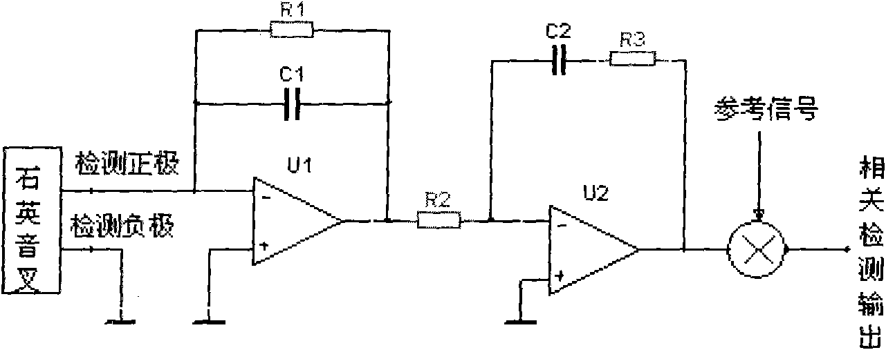
A technology for suppressing circuits and quartz tuning forks, applied in the direction of gyro effect for speed measurement, gyroscope/steering sensing equipment, measuring devices, etc., can solve the problems of temperature sensitivity, affecting dynamic range output, zero drift, etc. Effect

Inactive Publication Date: 2011-05-04
BEIJING INSTITUTE OF TECHNOLOGYGY
View PDF0 Cites 5 Cited by
  • Summary
  • Abstract
  • Description
  • Claims
  • Application Information

AI Technical Summary

Problems solved by technology

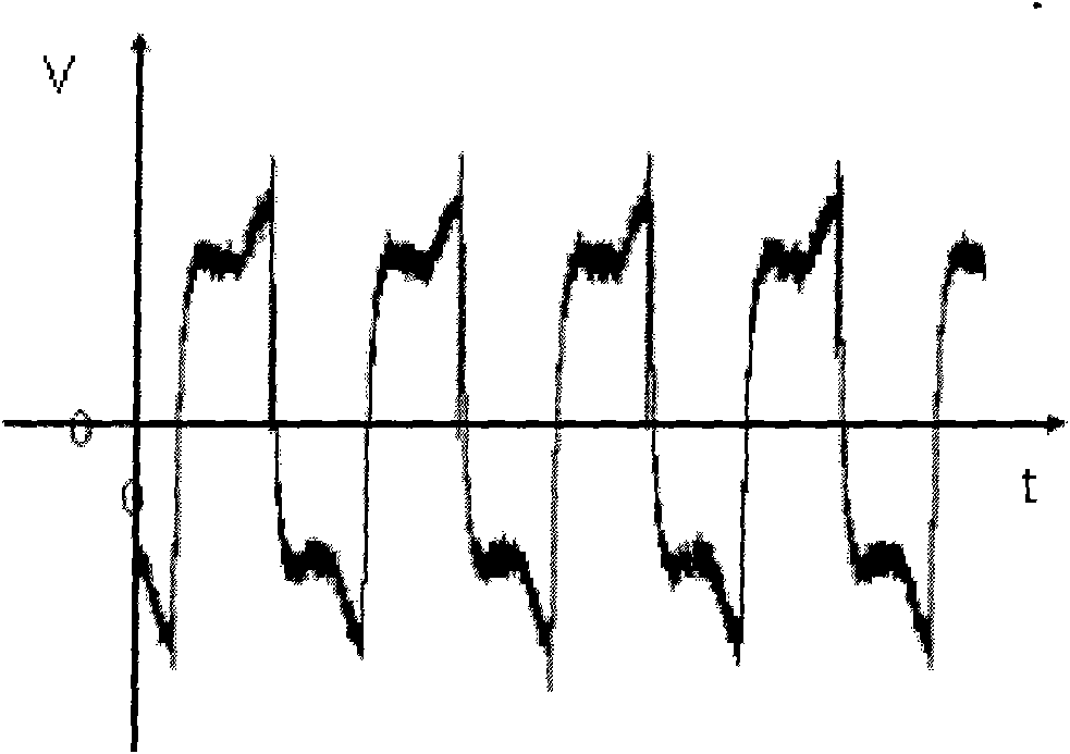
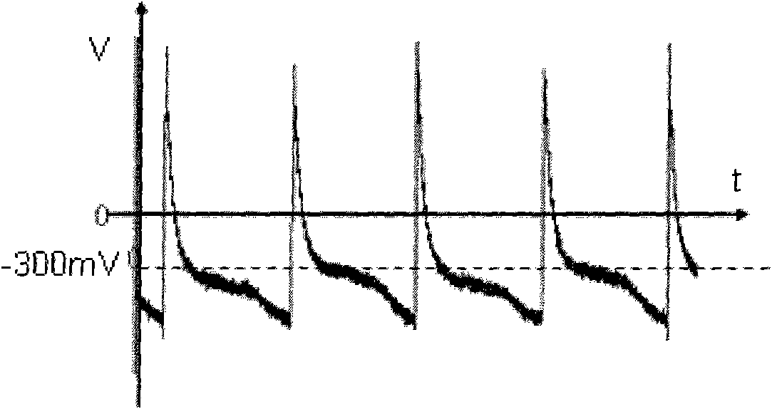
First of all, there are static coupling components and vibration coupling components in the DC voltage output by single-pole detection. If the static coupling and vibration coupling are large, the zero position will be too large, affecting the dynamic range and even directly saturating the output; secondly, the output signal of the single-pole detection circuit Directly affected by static and vibration coupling, which are sensitive to temperature and cause too much zero drift

Method used


Image

  • Coupling signal suppression circuit in quartz tuning fork gyroscope
  • Coupling signal suppression circuit in quartz tuning fork gyroscope
  • Coupling signal suppression circuit in quartz tuning fork gyroscope

Examples


Embodiment Construction

[0032] The design and control process of the inventive bipolar charge differential amplification and vibration coupling phase adjustment circuit will be described in detail below in conjunction with the accompanying drawings, so as to have a further understanding and recognition of the present invention.

[0033] Such as Figure 4 As shown, the bipolar charge differential amplification and vibration coupling phase adjustment circuit is composed of two parts: a circuit I for suppressing static coupling and a circuit II for adjusting vibration coupling, which is characterized in that it also includes:

[0034] Circuit I consists of three operational amplifiers (U 1 , U 2 , U 3 ), two precision capacitors (C 1 、C 2 ), four precision resistors (R 3 , R 4 , R 5 , R 6 ) and two large resistors (R 1 , R 2 )constitute.

[0035] where U 1 , U 2 is the same type of low bias current op amp, U 3 For a low offset low noise op amp, R 1 、C 1 , U 1 and R 2 、C 2 , U 2 form ...


PUM


Abstract

The invention relates to a coupling signal suppression circuit in a quartz tuning fork gyroscope. After signals output by a quartz tuning fork sensitive electrode pass through a static coupling suppression circuit, static coupling signals in a common mode state are effectively suppressed, and useful signals and differential mode interference signals are amplified; signals output by the static coupling suppression circuit are subjected to phase adjustment to ensure that the phase of mechanical coupling signals and the phase of related detection signals are orthogonal; and phase adjustment quantity realized by a phase adjustment circuit is marked as sigma, and the phase adjustment generates cos sigma gain for finally output useful signals and generates sin sigma gain for the mechanical coupling signals. The invention overcomes the defects that the traditional single-electrode detection circuit cannot suppress static coupling signals and cannot effectively suppress vibration coupling by adopting the technical scheme of double-electrode charge differential amplification and vibration coupling phase adjustment, not only completely suppresses the static coupling signals, but also provides conditions for effectively suppressing vibration coupling, and therefore, the performance of the microquartz tuning fork gyroscope is improved.

Description

technical field [0001] The invention belongs to the field of circuits for suppressing interference signals, in particular to a coupling signal suppressing circuit in a quartz tuning fork gyroscope. Background technique [0002] At present, the interference signal suppression method of quartz tuning fork gyro is based on the single-electrode signal correlation detection with lock-in amplifier as the core, that is, using the charge device to amplify the output charge of the positive pole of the quartz tuning fork gyro, and then compare the amplified signal with its inverse signal. The switch is gated, and then the high-frequency interference is filtered out through a low-pass filter to obtain a DC voltage signal proportional to the input angular velocity. [0003] The correlation detection principle with correlation detection as the core is: when the quartz tuning fork works in the driving resonance mode, if the angular velocity Ω is output in a specific direction, the output ...

Claims


Application Information

Patent Timeline
Patent Type & Authority Applications(China)
IPC IPC(8): G01C19/56G01C19/5614
Inventor 赵伟冯立辉崔芳孙雨南
Owner BEIJING INSTITUTE OF TECHNOLOGYGY
Learn More