Laser radar receiving optical system based on optical micro switch

A receiving optical system, laser radar technology, applied in the direction of radio wave measurement systems, instruments, etc., can solve the problems that the filter cannot suppress stray light, cannot achieve effective suppression, and stray light cannot be effectively suppressed, so as to overcome the difficulty of effective suppression Stray light outside the field of view, overcome the difficulty of accurately controlling the field of view, and suppress the effect of stray light

Active Publication Date: 2021-10-01
BEIJING INST OF CONTROL ENG
View PDF6 Cites 0 Cited by
  • Summary
  • Abstract
  • Description
  • Claims
  • Application Information

AI Technical Summary

Problems solved by technology

The hood can only suppress the stray light outside the field of view, and has no effect on the stray light in the field of view; the filter has a certain effect on suppressing the stray light in the field of view and the signal light in different spectrum bands, but the filter The chip cannot suppress the stray light in the same spectrum as the signal
In addition, because the optical system has a certain field of view, the bandwidth of the filter cannot be made very narrow, so the stray light within the bandwidth cannot be effectively suppressed
[0005] Therefore, the above traditional methods cannot achieve effective suppression of stray light inside and outside the field of view.

Method used


Image

  • Laser radar receiving optical system based on optical micro switch
  • Laser radar receiving optical system based on optical micro switch
  • Laser radar receiving optical system based on optical micro switch

Examples


Embodiment 1

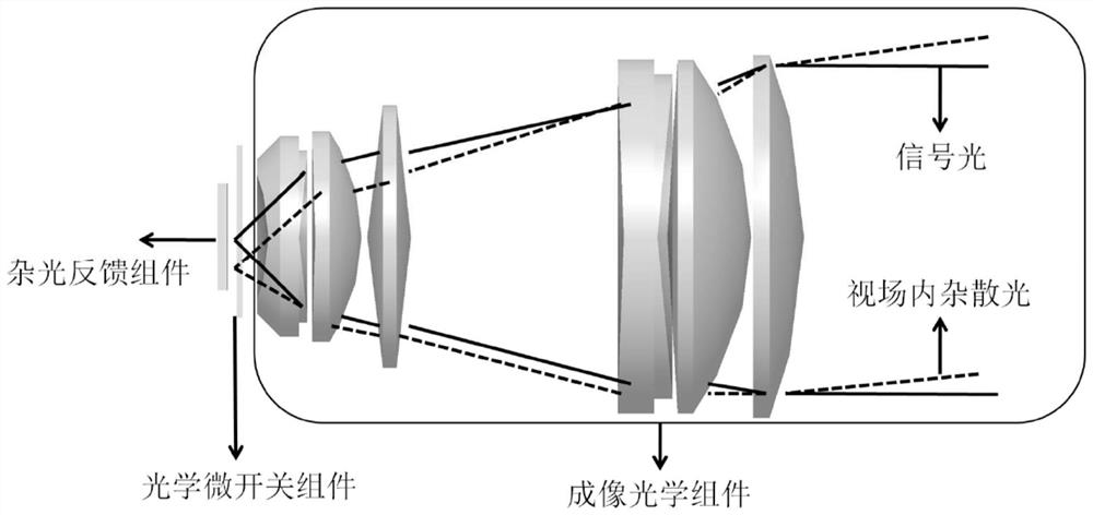
[0037] Such as figure 1 As shown, a lidar receiving optical system based on optical micro-switches, the system includes imaging optical components, optical micro-switches, stray light feedback components,

[0038] The signal light and stray light at the scanning point in the field of view first pass through the imaging optical component 1 , and the imaging optical component 1 focuses and images the signal light, and scatters and reflects the stray light. Secondly, through the optical micro switch 2, the optical micro switch 2 screens the signal light and the stray light, so that the signal light passes through and the stray light is absorbed. Finally, it reaches the stray light feedback component 3, and the stray light feedback component 3 sends instructions to the optical micro switch according to the light intensity information.

[0039] The imaging optical component is an image space telecentric optical system with a focal length of f=37.6mm and a half field of view of θ ...


PUM

PropertyMeasurementUnit
lengthaaaaaaaaaa

Abstract

The invention discloses a laser radar receiving optical system based on an optical micro switch. The laser radar receiving optical system comprises an imaging optical assembly, the optical micro switch and a stray light feedback assembly. The imaging optical assembly is used for imaging scanning points in a view field range; and the optical micro switch is located in front of the focus of the imaging optical assembly and comprises a plurality of sub-switches, and each sub-switch can be switched on and switched off independently. Transmission of light in a specific view field can be realized by controlling switching on and switching off of each sub-switch on the optical micro switch. The stray light feedback assembly can obtain the positions of signal light and stray light inside and outside the field of view on the optical micro switch through the switching on and switching off information of the sub-switches on the optical micro switch and the image gray scale information of different positions of the stray light feedback assembly. Transmission of the signal light and scattering of the stray light are achieved by controlling the switching on and switching off of the sub-switches at the corresponding positions on the optical micro switches. The system is simple in structural form, can accurately recognize the positions of the signal light and stray light inside and outside the field of view, and can assist in overcoming the problem that a traditional laser radar receiving optical system is difficult to suppress stray light in the field of view.

Description

technical field [0001] The invention belongs to the technical field of laser radar receiving optical systems, in particular to a laser radar receiving optical system based on an optical micro switch. Background technique [0002] During the planetary landing process, the probe needs to accurately identify the three-dimensional terrain of the planetary surface, so as to accurately navigate and avoid obstacles. In order to provide a larger maneuvering range for the detector, the obstacle avoidance sensor needs to have a longer working distance and a stronger ability to suppress stray light. [0003] The receiving optical system of the obstacle avoidance sensor focuses the scattered laser array scanning point energy on the chip. The receiving optical system must have super strong stray light suppression ability to meet the long-distance terrain recognition of the obstacle avoidance sensor. [0004] The traditional laser radar receiving optical system often uses a hood to supp...

Claims


Application Information

Patent Timeline
Patent Type & Authority Applications(China)
IPC IPC(8): G01S7/481
CPCG01S7/4816G01S7/4817Y02A90/10
Inventor 张运方朱飞虎张东来郭绍刚郑岩王立王晓磊于凡安娜李硕
Owner BEIJING INST OF CONTROL ENG
Why Eureka
Try Eureka