
Site large-scale direct shearing test device of shearing strength of concrete and basement adhesion surface

A technology of shear strength and test equipment, which is applied in the direction of testing material strength by applying stable shear force, can solve problems such as complicated operation, low test accuracy, and equipment installation error, and achieves wide application, high test accuracy, Applicable effect

Inactive Publication Date: 2011-05-04
TONGJI UNIV
View PDF0 Cites 35 Cited by
  • Summary
  • Abstract
  • Description
  • Claims
  • Application Information

AI Technical Summary

Problems solved by technology

[0004] However, the traditional on-site shear test operation is relatively complicated, especially in the preparation of specimens, equipment installation, and vertical load setting, which requires a lot of manpower and material resources; at the same time, the test accuracy is not high, mainly due to equipment installation errors, loading The instability of the system, the low degree of automation control, the use of manual operation to load the system, and the manual displacement measurement and reading are caused by factors such as
In addition, the application of vertical load and the shear velocity of shear load will greatly restrict the accuracy of test results
Therefore, the traditional on-site shear test method may not be able to meet the test requirements of high precision, high automation and low consumption

Method used


Image

  • Site large-scale direct shearing test device of shearing strength of concrete and basement adhesion surface
  • Site large-scale direct shearing test device of shearing strength of concrete and basement adhesion surface
  • Site large-scale direct shearing test device of shearing strength of concrete and basement adhesion surface

Examples


Embodiment

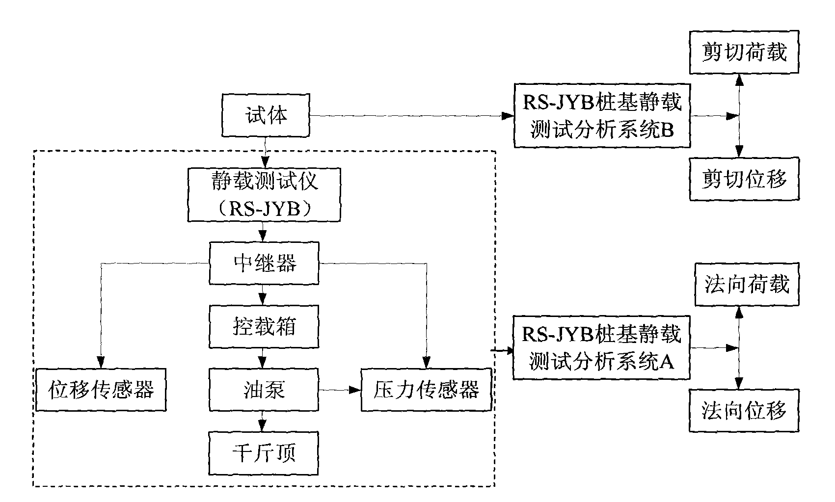
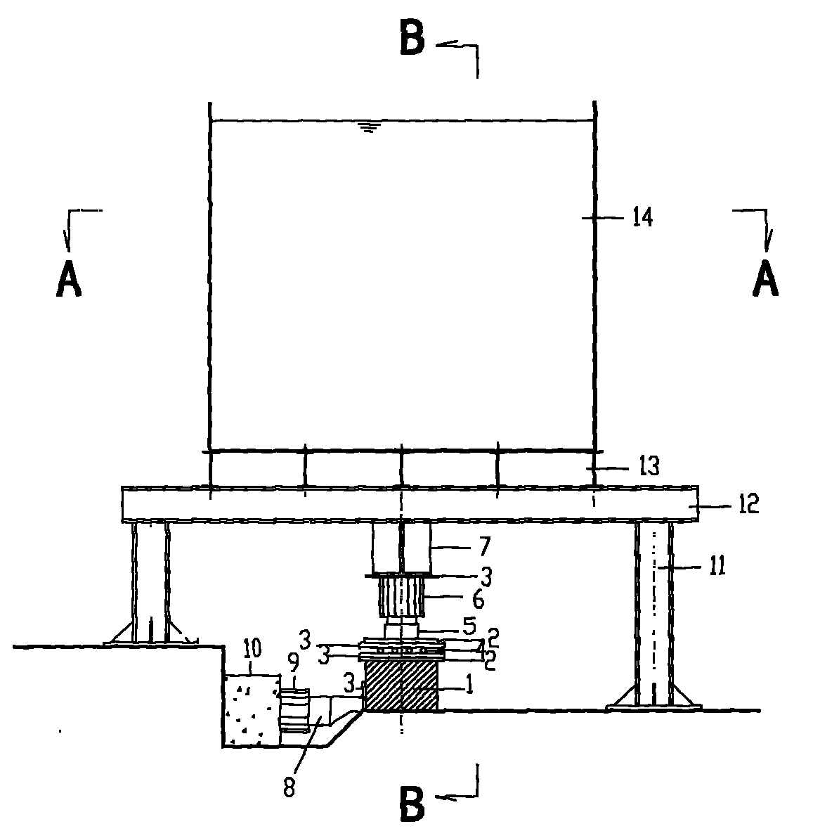
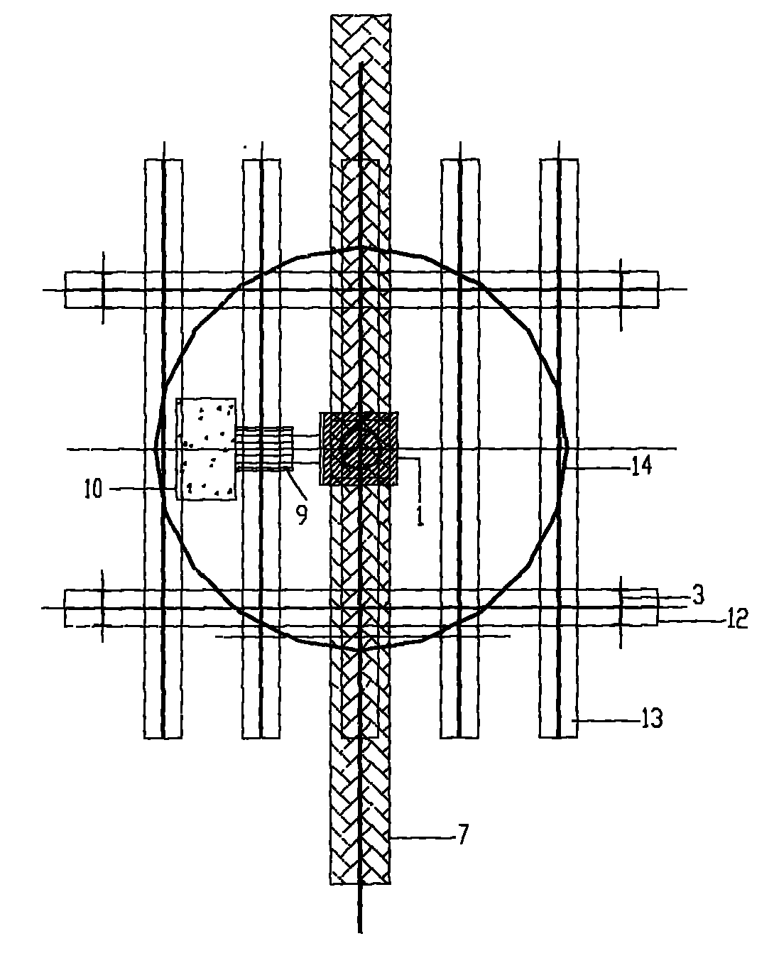
[0023] A direct shear test device for the shear strength of the cemented surface of concrete and bedrock, its structure is as follows figure 2 as shown, figure 2 The cross-sectional view of A-A in the middle is as follows image 3 as shown, figure 2 The cross-sectional view of B-B in the middle is as follows Figure 4 As shown: the device includes a circular backing plate 2, a square backing plate 3, a ball row 4, a transmission column 5, a vertical pile foundation static load test system 6, a reaction beam 7, a force transmission block 8, and a horizontal pile foundation static load test System 9, support column 11, beam 12, longitudinal beam 13, casing 14. Vertical pile foundation static load test system 6 controls vertical load application and vertical displacement data collection, and is connected to the top surface of test body 1 below reaction beam 7, and horizontal pile foundation static load test system 9 controls shear load application and shear load. The displ...


PUM


Abstract

The invention relates to a site large-scale direct shearing test device of the shearing strength of a concrete and basement adhesion surface, comprising two sets of independent pile foundation static load test systems, a bracket stand column, a cross beam, a counter-force beam, a longitudinal beam, a protective cylinder, a base plate and a force transferring block. One set of pile foundation static load test system controls the vertical displacement data collection application to the load and is connected to the top surface of a trail body below the counter-force beam; the other set of pile foundation static load test system controls shearing load application and shearing displacement data collection and is arranged between a concrete backseat and the side of the trail body; the cross beam is arranged above the bracket stand column; the counter-force beam is connected below the cross beam; the protective cylinder is connected with the cross beam through the longitudinal beam; and one side of the force transferring block is connected with the pile foundation static load test system and the other side is connected with the concrete trail body through the base plate. Compared with the prior art, the invention solves the problems of unstable loading system and complex counter-force system, really realizes full automation of static load test and has the advantages of strong applicability, wide application and higher precision.

Description

technical field [0001] The invention relates to a direct shear test device, in particular to an on-site large-scale direct shear test device for the shear strength of the bonded surface of concrete and bedrock. Background technique [0002] As one of the main load-bearing structures of the suspension bridge, the gravity anchor is mainly responsible for bearing the huge tension of the main cable, and is responsible for effectively and safely transmitting the tension of the main cable to the foundation through the frictional resistance between the anchorage foundation and the underlying bedrock, and Limit its horizontal displacement within the allowable value to ensure the safety of the entire suspension bridge, which is an important part to ensure the safety of the entire bridge. Therefore, in the design process, not only the weight of the anchorage must meet the basic requirements for the stress of the main cable; but also the shear strength of the cemented surface between t...

Claims


Application Information

Patent Timeline
IPC IPC(8): G01N3/24
Inventor 赖允瑾吴昌将张子新周生华
Owner TONGJI UNIV
Learn More