Polar coordinate wave-front curvature compensation method of synthetic aperture radar based on digital spotlight

A wavefront bending compensation and synthetic aperture radar technology, applied in the field of wavefront bending compensation, can solve problems such as accurate error compensation, and achieve the effect of solving accurate compensation, improving calculation efficiency, and solving wavefront bending errors

Inactive Publication Date: 2011-05-04
苏州杰岚德信息技术有限公司
View PDF4 Cites 11 Cited by
  • Summary
  • Abstract
  • Description
  • Claims
  • Application Information

AI Technical Summary

Problems solved by technology

[0005] The purpose of the present invention is to solve the problem of accurate compensation of the wavefront bending error of the SAR polar coordinate format algorithm under the co

Method used


Image

  • Polar coordinate wave-front curvature compensation method of synthetic aperture radar based on digital spotlight
  • Polar coordinate wave-front curvature compensation method of synthetic aperture radar based on digital spotlight
  • Polar coordinate wave-front curvature compensation method of synthetic aperture radar based on digital spotlight

Examples


Embodiment Construction

[0026] The present invention will be further explained in detail below in conjunction with the accompanying drawings and specific embodiments.

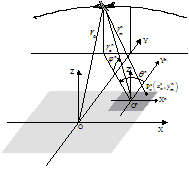
[0027] figure 1 It is the geometric model of spotlight SAR data acquisition. In order to verify the imaging capability under maneuvering conditions, it is assumed that the radar moves in a non-uniform straight line along a curved trajectory. The XYZ coordinate system is established with the center O of the scene irradiated by the radar beam as the origin, and the instantaneous distance from the radar to the center of the scene is recorded as r o (t), where t is the azimuth time. For the convenience of analysis, it is assumed that the ground scene irradiated by the radar beam is composed of point targets, and the whole scene is divided into several sub-blocks. Without loss of generality, it is assumed to be divided into N sub-blocks (only a few of them are drawn in the figure) , where the center of the nth sub-block is denoted as O ...


PUM


Abstract

The invention discloses a polar coordinate wave-front curvature compensation method of a synthetic aperture radar based on digital spotlight, comprising the following steps: (1) realizing segmentation of irradiation areas of radar beam by processing of improved digital spotlight and pre-filtering; (2) carrying out imaging processing on subwave beam data by utilizing a polar format algorithm (PFA), and realizing focused imaging of subscenes; and (3) carrying out seamless splicing on the images of the subscenes. By utilizing the polar coordinate wave-front curvature compensation method, the existing digital spotlight method is improved, repeated coarse focused imaging to the echo data (large data quantity) of the initial radar is avoided, and is replaced with the one-time coarse focused imaging of the initial data and the inverse imaging of a plurality of subwave beams (small data quantity), and the calculating efficiency of an algorithm can be obviously improved when multi-beam segmentation is carried out. Due to adoption of the polar coordinate wave-front curvature compensation method, the problem that the prior art can not compensate wave-front curvature errors of the pole format algorithm accurately under the large maneuvering condition of a radar platform can be solved.

Description

technical field [0001] The present invention relates to a synthetic aperture radar (synthetic aperture radar, referred to as SAR) imaging signal processing method, in particular to a synthetic aperture radar polar format algorithm (polar format algorithm, referred to as PFA) based on digital spotlight The wavefront bending compensation method. Background technique [0002] Spotlight SAR is a SAR working mode suitable for small scene and high resolution imaging. By controlling the antenna beam pointing, the radar transmits energy to continuously illuminate the same scene, which can break through the limitation of the antenna beam width, obtain a large synthetic aperture, and thus obtain a high azimuth resolution. Polar Format Algorithm (PFA) is a classic spotlight SAR imaging algorithm, such as literature 1: J.L.Walker, Range-Doppler imaging of rotating objects, IEEE Transactions on Aerospace and Electronic systems, vol.16, no.1, pp .23-52, January 1980. and Reference 2: D....

Claims


Application Information

Patent Timeline
IPC IPC(8): G01S7/02G01S13/90
Inventor 朱岱寅毛新华
Owner 苏州杰岚德信息技术有限公司
Why Eureka
Try Eureka