Vacuum switch tube

A vacuum switching tube and vacuum chamber technology, which is applied in the direction of electric switches, high-voltage/high-current switches, high-voltage air circuit breakers, etc., can solve the problems of insignificant increase in withstand voltage capacity and limited use, and improve the withstand voltage capacity. The effect of improving reliability and versatility

Inactive Publication Date: 2011-05-04
BEIJING BOE VACUUM ELECTRONICS CO LTD
View PDF5 Cites 24 Cited by
  • Summary
  • Abstract
  • Description
  • Claims
  • Application Information

AI Technical Summary

Problems solved by technology

When the vacuum fracture distance increases to a certain extent, the increase in its w

Method used


Image

  • Vacuum switch tube
  • Vacuum switch tube
  • Vacuum switch tube

Examples


Embodiment Construction

[0038] In order to make the purpose, technical solutions and advantages of the embodiments of the present invention clearer, the technical solutions in the embodiments of the present invention will be clearly and completely described below in conjunction with the embodiments of the present invention. It should be noted that, in the drawings or description, similar or identical elements all use the same reference signs.

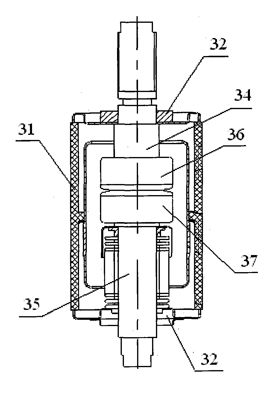
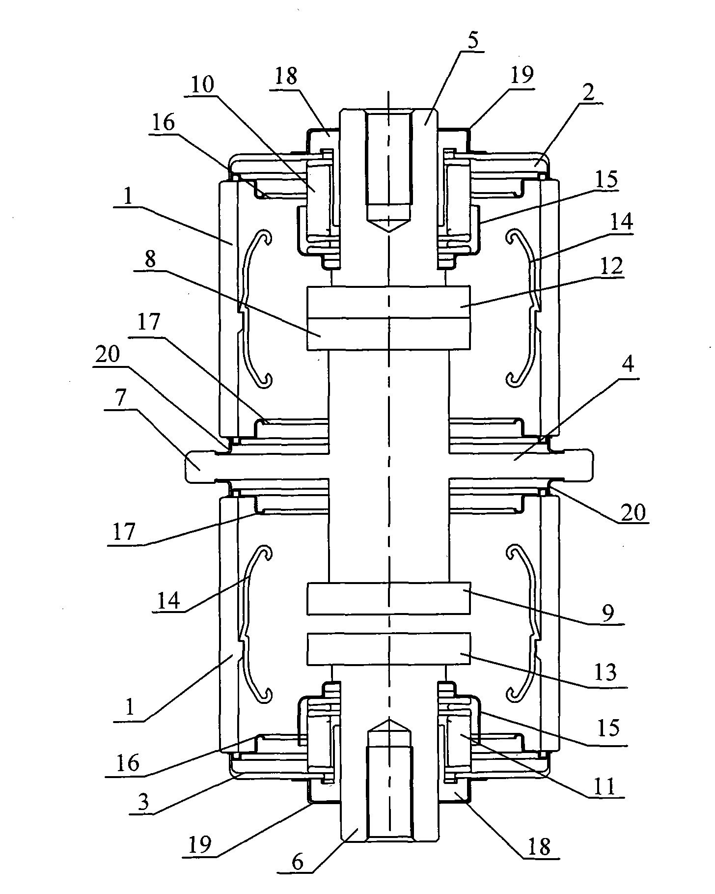
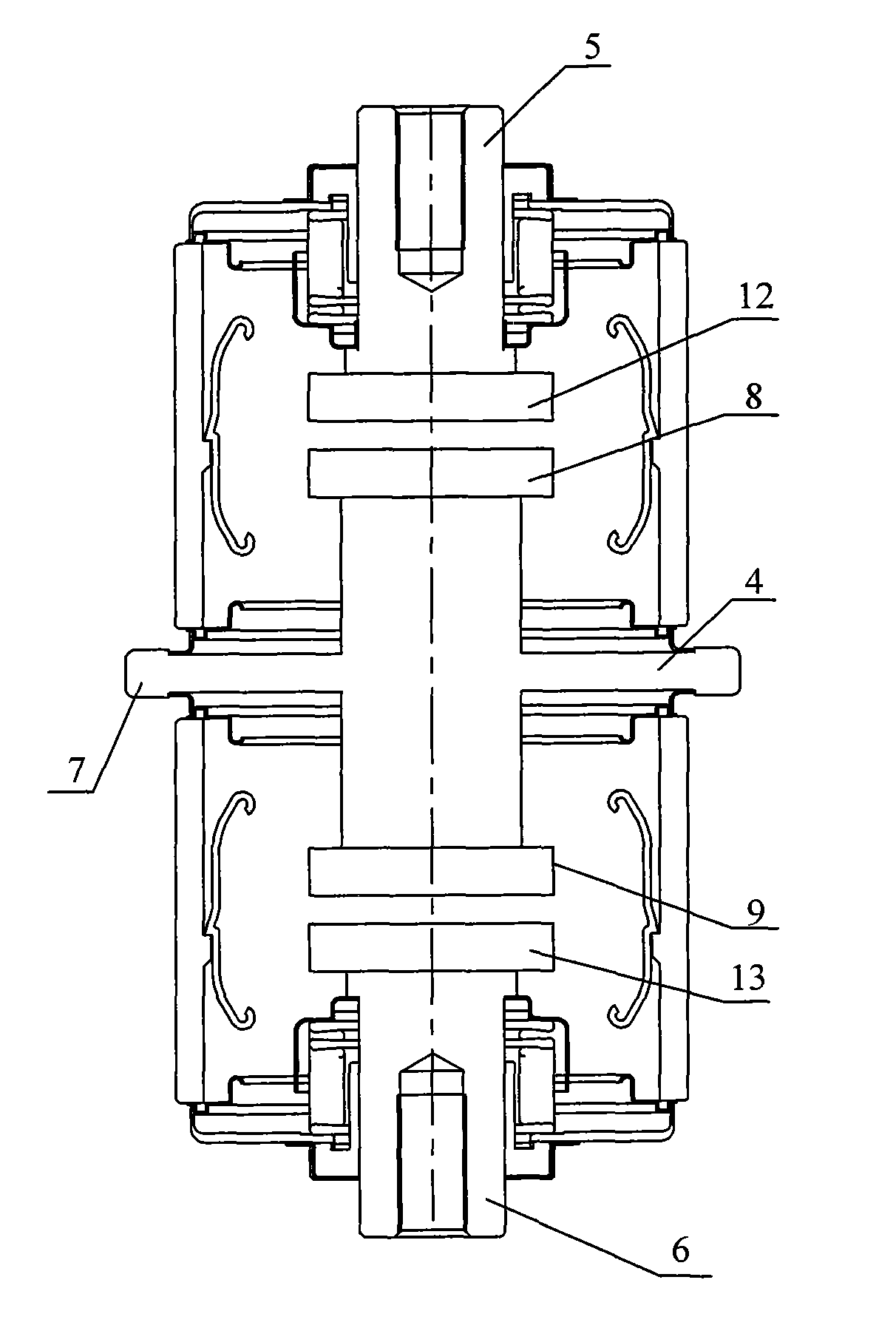
[0039] figure 2 A schematic structural diagram of a vacuum switch tube provided for an embodiment of the present invention, such as figure 2 As shown, the vacuum switch tube includes an insulating case 1 , an upper end cover 2 and a lower end cover 3 , the upper end cover 2 is sealed on the upper end of the insulating case 1 , and the lower end cover 3 is sealed on the lower end of the insulating case 1 . The material of the insulating shell 1 can specifically be ceramics or glass, which has good insulating properties. The vacuum switch tube also includes ...


PUM


Abstract

The invention provides a vacuum switch tube comprising an insulated case, an upper end cover, a lower end cover, a fixed conductive base, a first movable conducting rod and a second movable conducting rod, wherein the upper end cover is hermetically arranged at the upper end of the insulated case; the lower end cover is hermetically arranged at the lower end of the insulated case; the fixed conductive base comprises at least one joint and is fixedly arranged in the insulated case; the joints penetrate through the insulated case; the fixed conductive base is electrically and fixedly connected with a first fixed contact and a second fixed contact respectively; the first movable conducting rod penetrates through the upper end cover and first corrugated pipes connected with the inner sides of the upper end cover and is electrically and fixedly connected with a first movable contact arranged in a first vacuum chamber; and the second movable conducting rod penetrates through the lower end cover and second corrugated pipes connected with the inner sides of the lower end cover and is electrically and fixedly connected with a second movable contact arranged in a second vacuum chamber. The vacuum switch tube provided by the invention can realize three positions, thus improving the versatility.

Description

technical field [0001] The invention relates to a vacuum switch structure technology, in particular to a vacuum switch tube. Background technique [0002] The vacuum switch is an electrical device used to control and protect the power system. It realizes the closing and breaking of the circuit current by controlling the closing and separating of the two electrode contacts (hereinafter referred to as the contacts) in the vacuum switch tube, thereby To achieve the purpose of controlling the power system. The vacuum switch tube is the core component of the vacuum switch. It is a device that controls and extinguishes the arc through the contacts sealed in the vacuum container. [0003] The structure of the current common vacuum switch tube is as follows: figure 1 As shown, the tube body of the vacuum switch tube generally includes an insulating shell 31, metal end caps 32 arranged at the upper and lower ends of the insulating shell 31, a fixed conductive rod 34, a movable cond...

Claims


Application Information

Patent Timeline
IPC IPC(8): H01H33/66
Inventor 刘卫荣刘宝华王茂昌
Owner BEIJING BOE VACUUM ELECTRONICS CO LTD
Why Eureka
Try Eureka