Apparatus and process for the production of nanocarbon material
A technology for nano-carbon materials and manufacturing devices, which is applied in the direction of nano-structure manufacturing, nano-technology, nano-technology, etc., and can solve the problem of low yield of carbon materials
- Summary
- Abstract
- Description
- Claims
- Application Information
AI Technical Summary
Problems solved by technology
Method used
Image

Examples
Embodiment approach 1
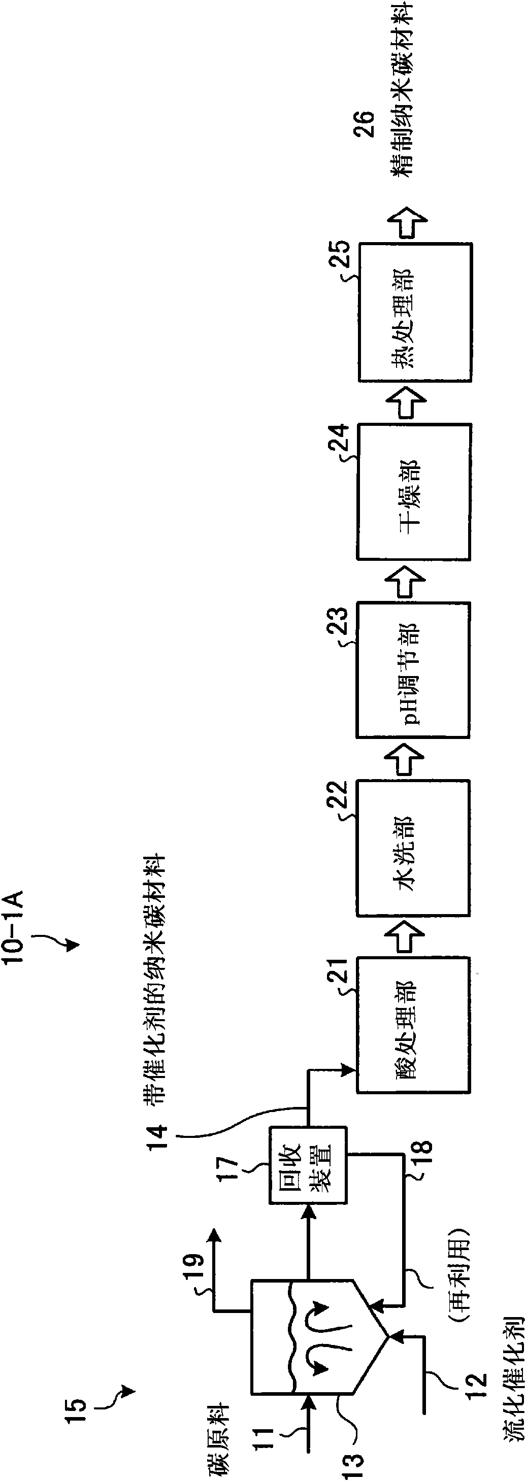
[0119] A schematic diagram of a carbon nanomaterial manufacturing device that prevents entanglement of carbon nanofibers by pH adjustment in this embodiment is shown in figure 1 .
[0120] Such as figure 1 As shown, the nano-carbon material manufacturing device 10-1A in the embodiment is equipped with: a nano-carbon material manufacturing unit 15 that utilizes a fluidized bed reactor to manufacture the nano-carbon material 14 with a catalyst; the obtained nano-carbon material 14 with a catalyst is dispersed In the acid solution, the fluidized catalyst 12 as the granulation catalyst is dissolved and separated with the acid solution 21; the washing part 22 is arranged on the downstream side of the acid treatment part 21, and the nano-carbon material after the acid treatment is washed with water; Be arranged on the downstream side of the above-mentioned water washing part 22, adjust the pH of the aqueous solution after washing to the weak base side with a medicament; the dryin...
Embodiment approach 2
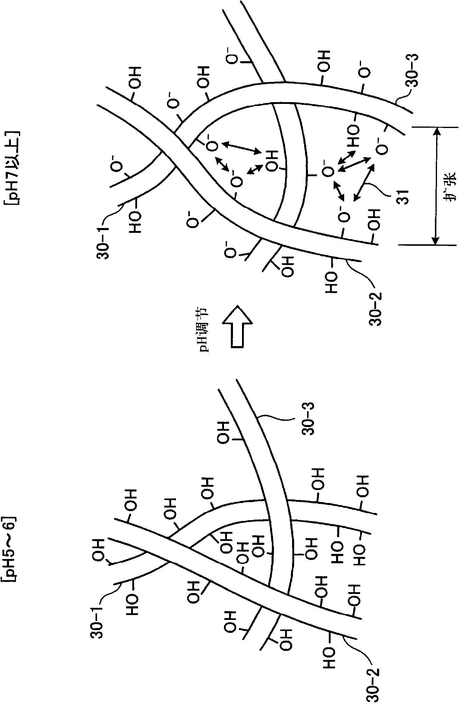
[0178] In this embodiment, the schematic diagram of the nano-carbon material manufacturing device for adding oxygen-containing functional groups is shown in Figure 6 . Figure 7 is a schematic diagram showing the behavior of nanocarbons caused by the repulsion of oxygen-containing functional groups. It should be noted that, for figure 1 The same configurations of the shown apparatuses according to the first embodiment are denoted by the same symbols, and descriptions thereof are omitted (the same applies hereinafter).
[0179] Such as Figure 6 As shown, the nano-carbon material manufacturing device 10-2A of Embodiment 2 is composed of the following parts: a nano-carbon material manufacturing part 15 that utilizes a fluidized bed reactor 13 to manufacture a nano-carbon material 14 with a catalyst; Oxygen-containing functional group addition treatment section 27 for adding oxygen-containing functional groups to the carbon material 14; dispersing the catalyst-bearing nano-c...
Embodiment approach 3
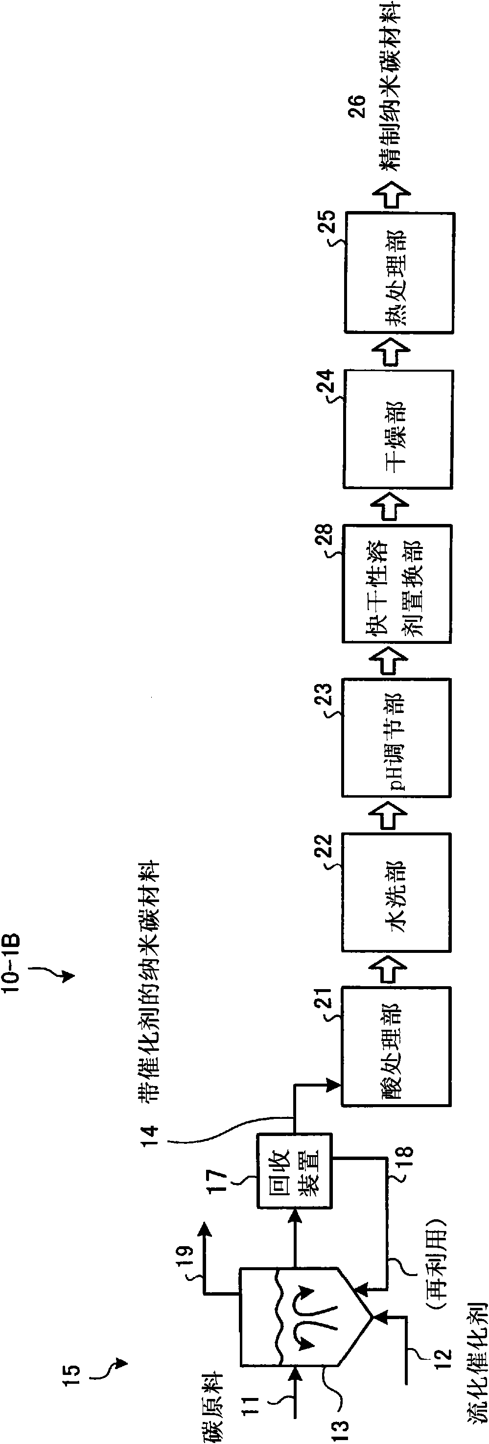
[0202] The schematic diagram of the nano-carbon material manufacturing device that implements the treatment of replacing with a fast-drying solvent in Embodiment 3 is shown in Figure 12 .
[0203] Such as Figure 12As shown, the nano-carbon material manufacturing device 10-3A of the embodiment is equipped with: a nano-carbon material manufacturing unit 15 that manufactures a nano-carbon material 14 with a catalyst through a fluidized bed reactor 13; and disperses the obtained nano-carbon material 14 with a catalyst. In the acid solution, the fluidized catalyst 12 as the granulation catalyst is dissolved and separated with the acid solution 21; the washing part 22 is arranged on the downstream side of the acid treatment part 21, and the nano-carbon material after the acid treatment is washed with water; Set on the downstream side of the above-mentioned water washing part 22, a quick-drying solvent replacement part 28 replaced with a quick-drying solvent; and a drying part 24 ...
PUM
| Property | Measurement | Unit |
|---|---|---|
| particle diameter | aaaaa | aaaaa |
| particle diameter | aaaaa | aaaaa |
| aperture size | aaaaa | aaaaa |
Abstract
Description
Claims
Application Information
 - R&D
- Intellectual Property
- Life Sciences
- Materials
- Tech Scout
- Unparalleled Data Quality
- Higher Quality Content
- 60% Fewer Hallucinations
Browse by: Latest US Patents, China's latest patents, Technical Efficacy Thesaurus, Application Domain, Technology Topic, Popular Technical Reports.
© 2025 PatSnap. All rights reserved.Legal|Privacy policy|Modern Slavery Act Transparency Statement|Sitemap|About US| Contact US: help@patsnap.com