Application method of loop slurry reactor adopting novel filtration module

A loop reactor and filter assembly technology, applied in chemical instruments and methods, chemical/physical processes, etc., can solve the problems of complex equipment structure, complicated equipment, complicated operation, etc., to improve separation efficiency, improve reaction performance, and save reactions. effect of space

Active Publication Date: 2013-06-05
CHINA PETROLEUM & CHEM CORP +1
View PDF4 Cites 4 Cited by
  • Summary
  • Abstract
  • Description
  • Claims
  • Application Information

AI Technical Summary

Problems solved by technology

[0006] WO 94 / 16807 discloses a method of using a filter assembly in a reactor to achieve liquid-solid separation, but once the catalyst particles block the filter assembly, the regeneration of the filter assembly is difficult, so it is not suitable for large-scale continuous production
[0007] CN1589957A discloses that a primary separation unit is set inside the reactor, a secondary separation unit is set outside the reactor to realize liquid-solid separation, and a recoil unit is set outside the reactor to realize the continuous operation of filtration, which not only takes up The reaction space in the reactor also leads to complex equipment structure and complicated operation
This liquid-solid separation method requires the help of external power, and does not provide a detailed backwashing method, making it difficult to achieve continuous and effective separation of liquid and solid
[0010] From the above analysis, it can be seen that it is difficult to achieve continuous operation by means of filtration. Even if continuous operation is realized, it will cause serious wear of solid catalyst particles, and it will also make the equipment complicated, and the investment and operating costs will increase.

Method used


Image

  • Application method of loop slurry reactor adopting novel filtration module
  • Application method of loop slurry reactor adopting novel filtration module
  • Application method of loop slurry reactor adopting novel filtration module

Examples


Embodiment

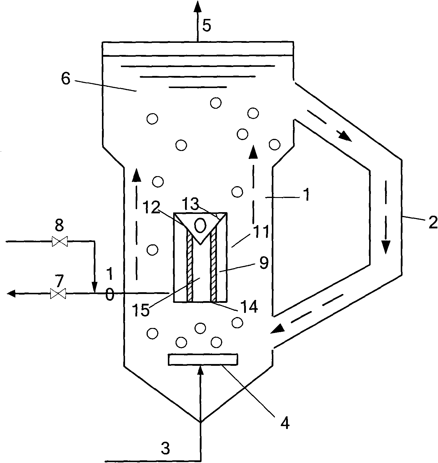
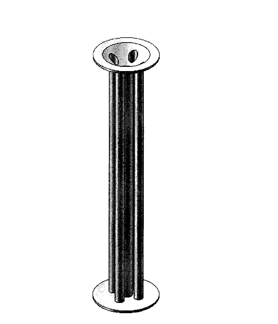
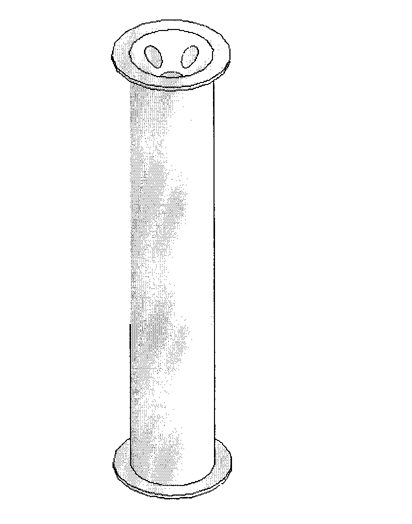
[0039] Attached figure 1 The slurry bed loop reactor shown, wherein the diameter ratio of the settling zone of the slurry bed loop reactor and the lower part of the riser is 1.5:1, the ratio of the diameter of the riser to the downcomer is 4:1, and the filter assembly The ratio to the diameter of the riser is 1:10. The internal structure of the filter assembly is attached figure 2 , the cone angle 13 of the upper isolation plate of the filter assembly is 45°. Each filter tube has a diameter of 50 mm and a length of 1000 mm. The filter tube is made of sintered porous metal filter tube with an average pore size of 1 μm. The catalyst used in the slurry zone 11 is an iron-based catalyst with a particle size ranging from 1 to 100 μm.

[0040] The synthesis gas is introduced from the gas inlet 3 at the bottom of the riser, and enters the reaction zone of the slurry bed reactor in the form of bubbles through the gas distributor 4. The synthesis gas is in contact with the solid ca...


PUM


Abstract

The invention discloses an application method of a loop slurry reactor adopting a novel filtration module. In the method, synthesis gas firstly enters a riser of the loop slurry reactor from the bottom of the reactor, and then is mixed with the slurry in the riser for reaction, wherein the interior of the riser is provided with the filtration module, and the upper end of an internal flow passage of the filtration module is of a reverse conical structure with a cone angle of 20 degrees to 70 degrees; the slurry flows upwardly along the riser, part of the slurry flows into the internal flow passage of the filtration module, and clear solution penetrates through the wall of a filter tube and serves as a product to be discharged out of the slurry reactor through a discharge hole; and the filtered and condensed slurry continuously flows upwardly and then enters a settlement zone with an enlarged pipe diameter at the top; and the slurry, most bubbles of which are removed in the settlement zone, enters a downcomer, and then is circulated to the riser through the downcomer so as to be subjected to reaction continuously. The method provided by the invention has the advantages of long working cycle of the filtration module and high liquid-solid separation efficiency; and simultaneously, the method provided by the invention is favorable for uniform distribution of the gas flow and liquidflow in the reaction zone of the riser, thus the utilization efficiency of the reactor is increased.

Description

technical field [0001] The invention relates to a gas-liquid-solid three-phase slurry bed reactor and equipment and methods for separating solid particles from liquid products, more specifically, to a slurry bed loop reactor, and realizes liquid products and A device for continuous separation of solid particles and an application method thereof. Background technique [0002] The slurry bed reactor is a commonly used gas-liquid (slurry) contact reaction equipment with a very high liquid storage capacity. For the catalytic reaction process with large reaction heat, the use of slurry bed reactor can effectively remove the reaction heat, realize the isothermal operation of the reactor, and ensure the normal operation of the reactor, so it has been widely used in today's chemical process. The slurry bed loop reactor is a high-efficiency heterogeneous reactor developed on the basis of the slurry bed bubbling reactor. In addition to all the advantages of the slurry bed bubbling r...

Claims


Application Information

Patent Timeline
Patent Type & Authority Patents(China)
IPC IPC(8): B01J8/22
Inventor 唐晓津胡立峰张占柱王少兵
Owner CHINA PETROLEUM & CHEM CORP
Why Eureka
Try Eureka