Polygonal brake device

A braking device, polygonal technology, applied in the direction of the hoisting device, etc., can solve the problems of the spring arrangement of the brake being too tight or interfering, the design arrangement space is small, and the material waste, so as to reduce the cost and material waste, The parallelism is easy to guarantee and the effect of economical use

Active Publication Date: 2011-05-11
ZHEJIANG MATO DRIVE EQUIP
View PDF4 Cites 1 Cited by
  • Summary
  • Abstract
  • Description
  • Claims
  • Application Information

AI Technical Summary

Problems solved by technology

As we all know, the metal circular processing technology requirements are relatively simple, but the material waste is high, and the relative cost is high
Therefore, there is a contradiction in terms of cost savings using a brake device with a circular structure
Moreover, compared to the stability of the plane, the circular one has a small area and a small design arrangement space, which leads to too tight or interference in the arrangement of the springs, bolts, pins, etc. of the brake.

Method used


Image

  • Polygonal brake device
  • Polygonal brake device
  • Polygonal brake device

Examples


Embodiment 1

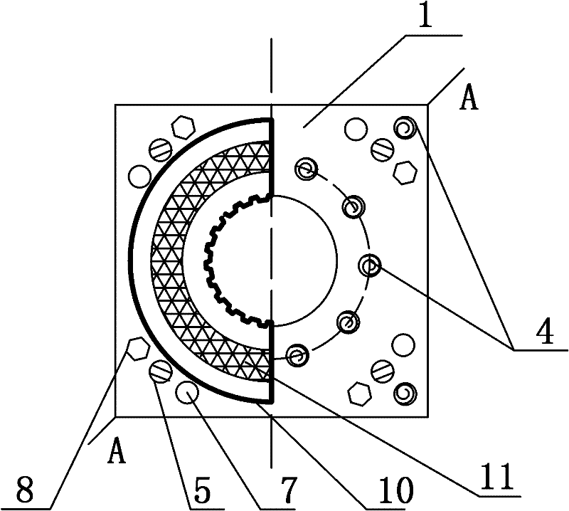
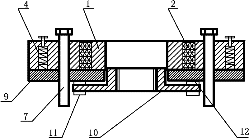
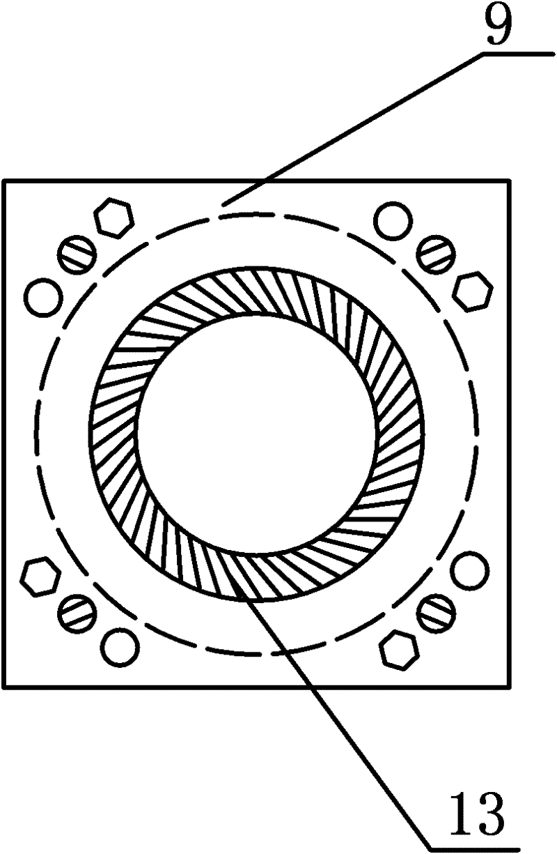
[0022] Example 1. A polygonal detent such as figure 1 and figure 2 As shown, it includes an iron core assembly. The iron core assembly is provided with a guide pin 5 connected to the armature 9. A brake disc 10 is clamped between the armature 9 and the traction machine. Friction plates 11 are provided on both sides of the brake disc 10, and It is connected with the rotating shaft of the traction machine through a spline, and it is characterized in that: the iron core assembly includes a polygonal (can be square) iron core, and a ring coil 2 is arranged in the slot on the iron core, and the corresponding iron core assembly The armature 9 is also polygonal (square), and the connection structures between the iron core 1 and the armature 9 are all arranged on the four corners of the polygonal (square). The connection structure includes a guide pin 5 , a fixing bolt 7 passing through the iron core 1 and the armature 9 to connect with the traction machine, and an anti-jack bolt 8...

Embodiment 2

[0023] Example 2. A polygonal detent such as figure 1 and figure 2 As shown, it includes an iron core assembly. The iron core assembly is provided with a guide pin 5 connected to the armature 9. A brake disc 10 is clamped between the armature 9 and the traction machine. Friction plates 11 are provided on both sides of the brake disc 10, and It is connected with the rotating shaft of the traction machine through a spline, and it is characterized in that: the iron core assembly includes a polygonal (square) iron core, and a ring coil 2 is arranged in the slot on the iron core, and the armature 9 corresponding to the iron core assembly It is also a polygon (square), and the connection structures between the iron core 1 and the armature 9 are all arranged on the four corners of the polygon (square). The connection structure includes a guide pin 5 , a fixing bolt 7 passing through the iron core 1 and the armature 9 to connect with the traction machine, and an anti-jack bolt 8 pa...


PUM


Abstract

The invention relates to a polygonal brake device comprising an iron core assembly. The iron core assembly is provided with a guide pin (5) connected with an armature (9); a brake disk (10) is clamped and fixed between the armature (9) and a traction machine; both sides of the brake disk (10) are provided with friction plates (11), and the brake disk (10) is connected with a rotating shaft of thetraction machine through a spline. The polygonal brake device is characterized in that the iron core assembly comprises a polygonal iron core, a slot positioned on the polygonal iron core is internally provided with an annular coil (2); the armature (9) which corresponds to the iron core assembly is of a polygon; the connecting structures of the iron core (1) and the armature (9) are all arrangedon corners of the polygon. The invention can enhance the brake effect of the brake device and reduce the processing process of the brake device, thereby saving the production cost.

Description

technical field [0001] The invention relates to a braking device, in particular to a polygonal braking device for an elevator traction machine. Background technique [0002] At present, with the continuous development of the national economy and the improvement of people's living standards, modern high-rise buildings are spread all over urban and rural areas. In order to ensure the rapid and safe flow of people in high-rise buildings, meet the fast-paced needs of modern life, and improve the operating efficiency and equipment performance, the design and manufacture requirements for elevators are getting higher and higher. The braking performance of the traction machine directly affects the safety and effectiveness of the elevator. The existing traction machine braking devices have many structural forms, and the use of circular structures can reduce the use of metal materials. Electromagnetic braking devices are generally circular structures (including iron cores, armatures ...

Claims


Application Information

Patent Timeline
Patent Type & Authority Applications(China)
IPC IPC(8): B66D5/14B66D5/30
Inventor 施加松周建华
Owner ZHEJIANG MATO DRIVE EQUIP
Why Eureka
Try Eureka