Novel engine

An engine, a new type of technology, applied in the direction of machines/engines, hot gas variable displacement engine devices, mechanical equipment, etc., can solve the problems of low conversion efficiency, low work efficiency and pollution, and the engine is easy to pollute the environment, so as to achieve low operating cost and structure Simple, low-polluting effect

Active Publication Date: 2011-05-11
安徽网萌科技发展股份有限公司
View PDF5 Cites 0 Cited by
  • Summary
  • Abstract
  • Description
  • Claims
  • Application Information

AI Technical Summary

Problems solved by technology

[0005] A new type of engine provided by the present invention aims at overcoming the disadvantages of existing engines such as easy pollution of the environment and low conversion efficiency, and to provide an external combustion engine with high work efficiency and low pollution

Method used


Image

  • Novel engine
  • Novel engine
  • Novel engine

Examples


Embodiment 1

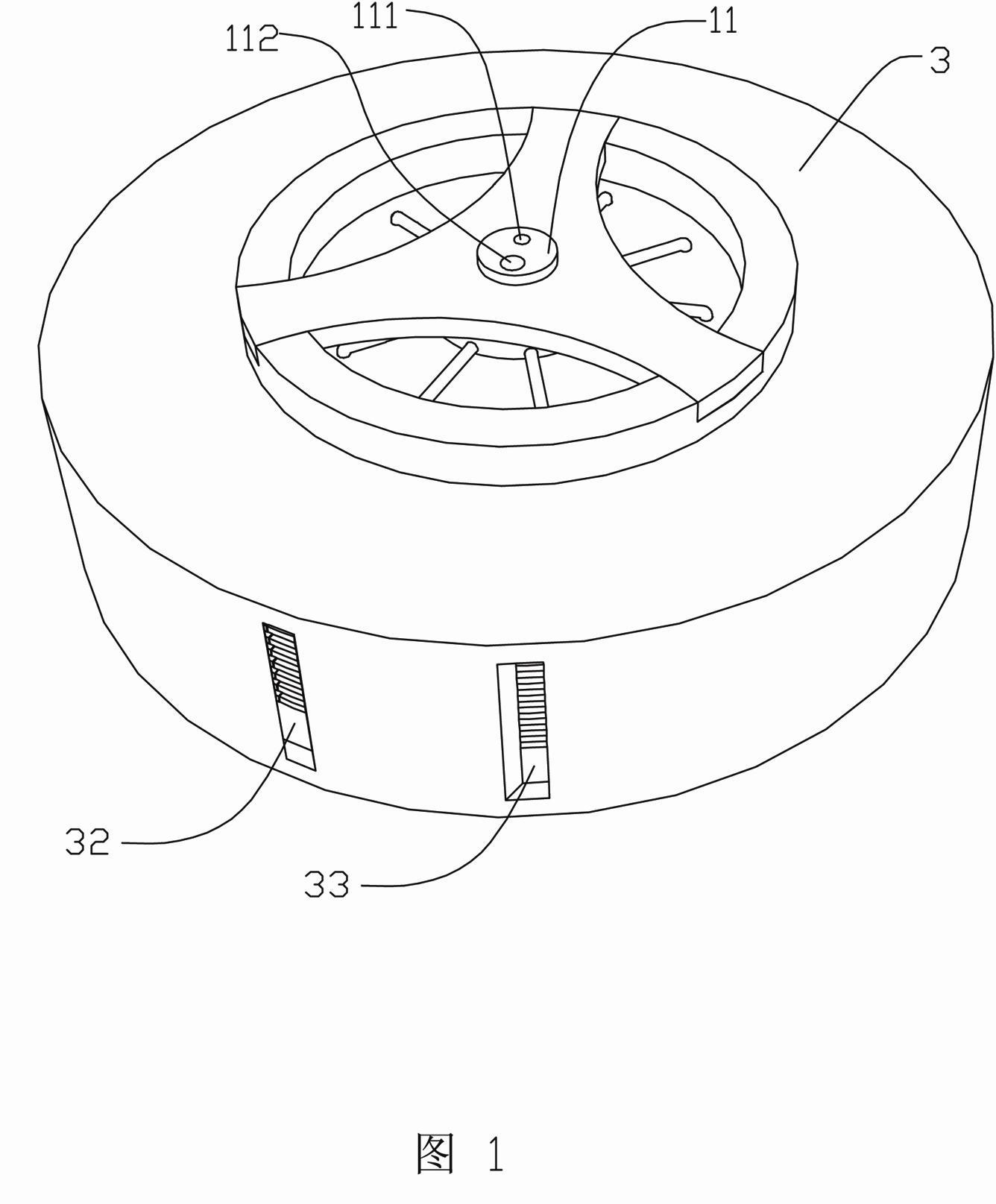
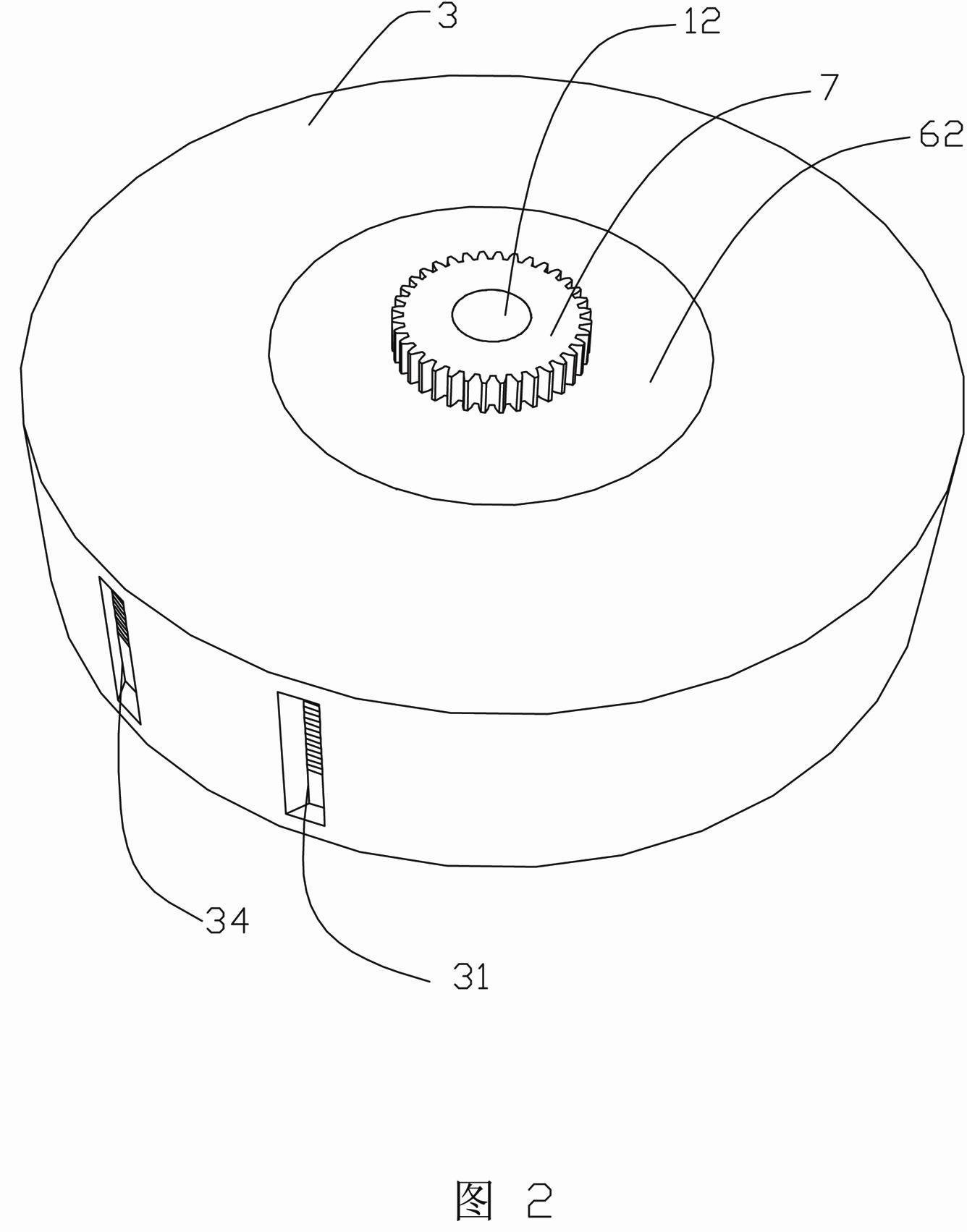
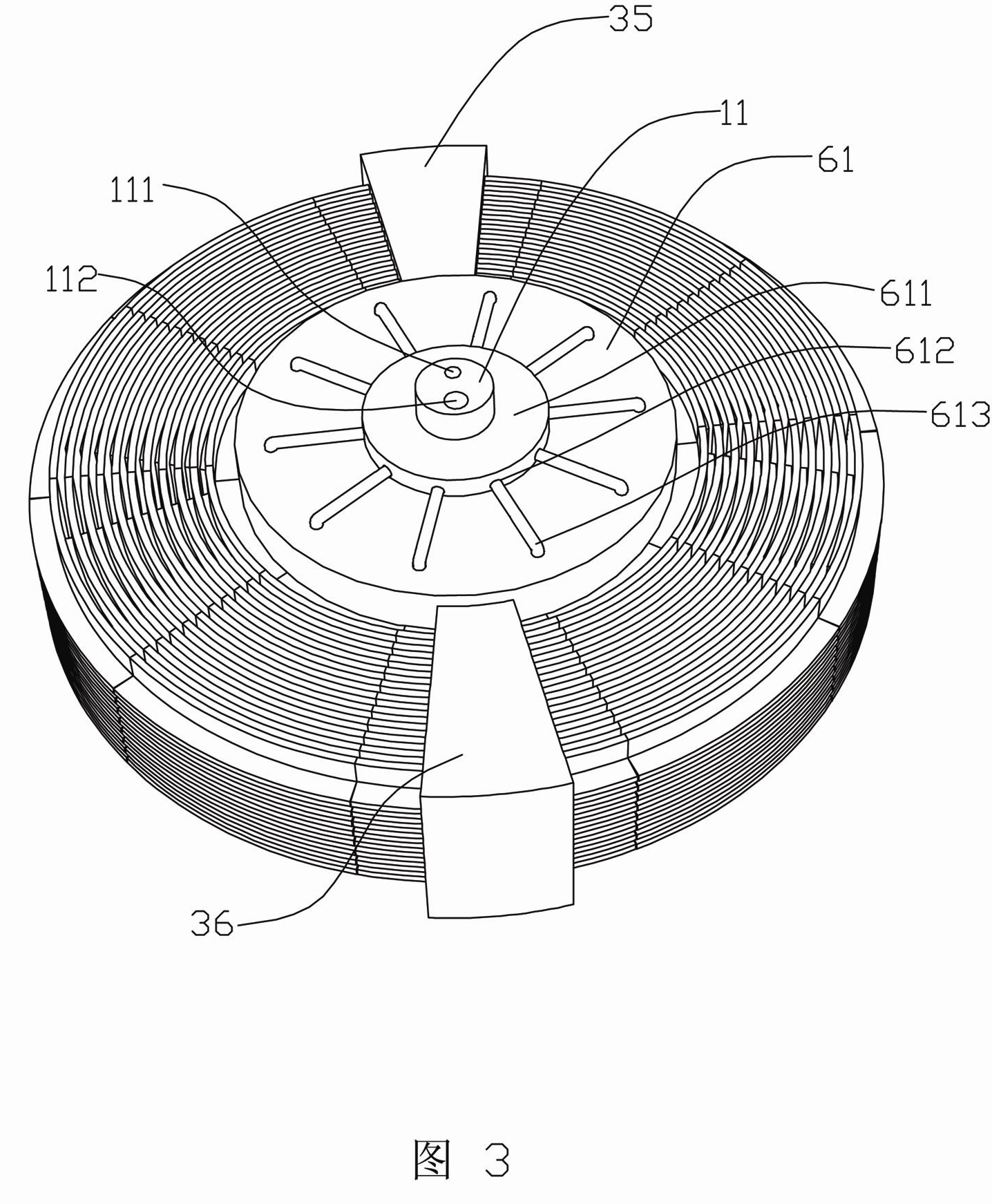
[0040] Such as figure 1 , figure 2 , image 3 , Figure 4 , Figure 5 , Figure 6 , Figure 7Shown, a kind of novel engine comprises two shaft rods 11,12 which are arranged on the central axis and are symmetrical up and down, a plurality of cylinders 2 which are evenly distributed around the shaft rods 11,12 and rotate around the shaft rods 11,12, and are arranged on the cylinder The piston 21 in 2 and the casing 3 that surrounds the cylinder 2 and is rotatably connected with the cylinder 2, the casing 3 is connected with the shaft rod 11; the piston 21 is provided with a piston rod 211, and the piston rod 211 is connected with two symmetrical shafts up and down. The connection blocks 41, 42 whose center deviates from the above-mentioned central axis, the connection blocks 41, 42 are rotatably connected with the piston rod 211; the connection points of the connection blocks 41, 42 and the piston rod 211 are symmetrical about the axis of the connection blocks 41, 42, The...

Embodiment 2

[0048] refer to Figure 8 , Figure 9 , Figure 10 , Figure 11 , Figure 12 , Figure 13 , Figure 14 . A new type of engine, which is arranged on the central axis and has two symmetrical shafts 11, 12 up and down, a plurality of cylinders 2 evenly distributed around the two shafts, a piston 21 arranged in the cylinder 2, and a cylinder that can be wound around the cylinder 2 2 connected housing 3, the housing 3 is connected with the shaft rod 12; the piston 21 is provided with a piston rod 211, and the piston rod 211 is connected with two connection blocks 41, 42 which are symmetrical up and down and whose axes deviate from the above-mentioned central axis. The blocks 41, 42 are rotatably connected to the piston rod 211, and the connection points between the connecting blocks 41, 42 and the piston rod 211 are symmetrical about the axis of the connecting blocks 41, 42, and the axis of the connecting block 41 is connected to the shaft 11 through the connecting part 51 ,...


PUM


Abstract

The invention discloses a novel engine which comprises two shaft levers, a plurality of air cylinders, pistons and a casing, wherein the two shaft levers are arranged on a central axis and are symmetrical up and down; the plurality of air cylinders are uniformly distributed around the two shaft levers; the pistons are arranged in the air cylinders; the casing encircles the exteriors of the air cylinders and is rotatably connected with the air cylinders in a sealing mode, and the casing is connected with the shaft levers; the pistons are provided with piston rods; the piston rods are connected with two connecting blocks which are symmetrical up and down, and the axle centers of the two connecting blocks deviate the central axis; the connecting points of the connecting blocks and the piston rods are symmetrical relative to the axle centers of the connecting blocks; the axle centers of the upper and lower connecting blocks are respectively connected with the upper and lower shaft levers through connecting parts; and the two symmetrical ends of the casing relative to the central axis are respectively provided with a cooling material inlet, a heating material outlet and a cooling material outlet and a heating material inlet. The engine has a simple structure, is convenient to use, is high in efficiency, low in noise, less in pollution and low in operating cost is low, and is suitable for various energy sources; and because continuous combustion is adopted, the fuel combustion efficiency is higher, and the engine is suitable for the fuel with higher impurity content.

Description

technical field [0001] The invention relates to the field of engines, in particular to a novel external combustion engine with high working efficiency. Background technique [0002] Existing internal combustion engines are widely used in various fields, especially in the automotive field, the number of internal combustion engines is the largest, and internal combustion engines have brought great convenience both in industrial production and in people's work and life. However, due to the thermal energy and mechanical energy of internal combustion engines The conversion efficiency is generally between 20%-40%, and the remaining 60%-80% of the heat energy cannot be used and needs to be discharged outside, which wastes a lot of energy. At the same time, because the fuel cannot be completely burned, there is a large amount of air-polluting gas in the tail gas. The air is seriously polluted. According to statistics, these gases are one of the main reasons for the warming of the ea...

Claims


Application Information

Patent Timeline
Patent Type & Authority Applications(China)
IPC IPC(8): F02G1/044
Inventor 林水龙
Owner 安徽网萌科技发展股份有限公司
Why Eureka
Try Eureka