Flow path switch control device

A switch control and flow path technology, applied in the field of switch devices and flow path switch control devices, can solve the problems of increasing the flow area of ​​the pressure balance control loop, increasing the pressure difference, etc., to avoid strong vibration and noise, and to avoid the opening and closing process. smooth effect

Inactive Publication Date: 2011-05-11
ZHEJIANG SANHUA CLIMATE & APPLIANCE CONTROLS GRP CO LTD
View PDF4 Cites 6 Cited by
  • Summary
  • Abstract
  • Description
  • Claims
  • Application Information

AI Technical Summary

Problems solved by technology

[0005] The technical problem to be solved by the present invention is to control and slow down the change of the fluid pressure passing through the valve device by improving the large-diameter electromagnetic switch structure of the prior art in the refrigeration system, and gradually increase the pressure during the valve opening process Balance the flow area of ​​the fluid in the control circuit to gradually increase the pressure difference between the front and back of the valve body, so that the valve opens smoothly without strong impact and vibration, and avoids strong vibration and noise generated by the electromagnetic switch at the moment of high pressure difference action problem, for this reason the present invention adopts the following scheme:

Method used


Image

  • Flow path switch control device
  • Flow path switch control device
  • Flow path switch control device

Examples


Embodiment Construction

[0036] In order to enable those skilled in the art to better understand the technical concept of the present invention, the opening process of the flow path switch control device will be further described in detail below with reference to the drawings and embodiments.

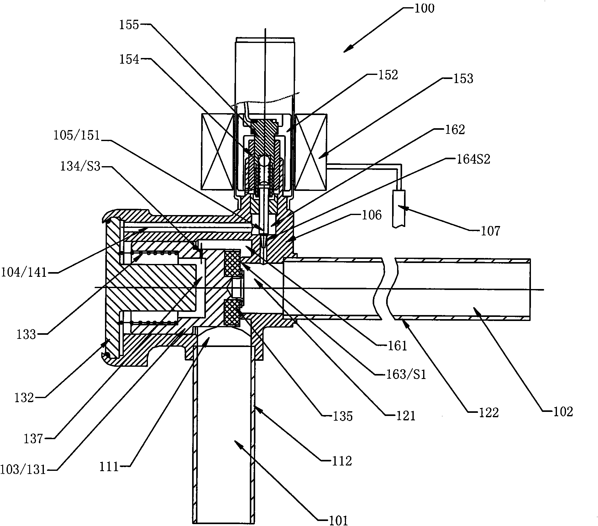
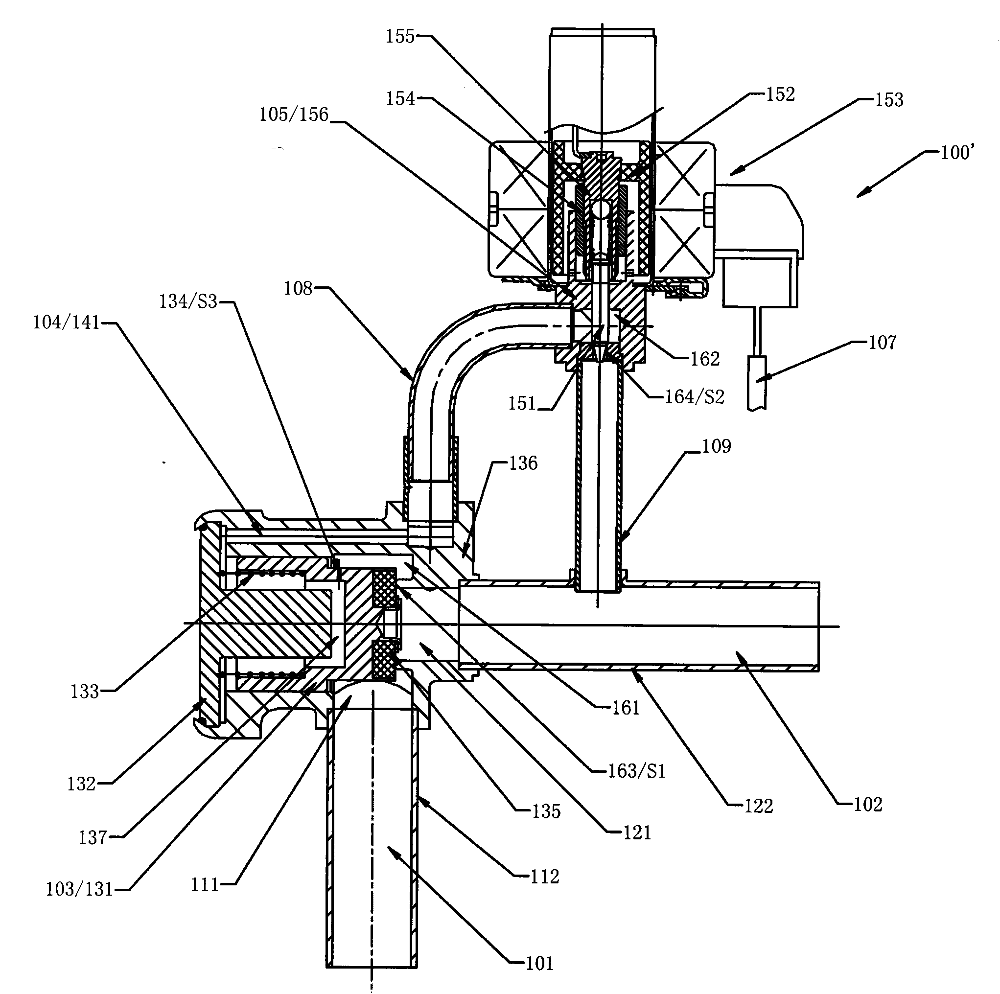
[0037] figure 1 It is a specific structural diagram of a flow path switch control device given in the present invention.

[0038] Such as figure 1 As shown, the flow path switch control device 100 includes a metal material integrally formed cover body 106, the valve device 103 and the adjustment device 105 are airtightly installed on the cover body 106, and an inlet chamber 111 and an outlet chamber are also formed on the cover body 106. The mouth chamber 121, the inlet connecting pipe 112 and the inlet chamber 111 are airtightly welded and connected, and the outlet connecting pipe 122 is airtightly welded and connected with the outlet chamber 121. In this way, through the fluid inlet 101 --- the inlet chamb...


PUM


Abstract

The invention discloses a flow path switch control device which is used for control systems, such as heating ventilating and air conditioning, refrigeration and the like. In the prior art, because the pressure of the upper part of a piston instantaneously lowers at the moment that a pilot valve is switched on and off, a larger pressure difference is formed between the upper part and the lower part of the piston to push the piston to move so as to generate strong impact with a piston stopping component, and the service life of a product and the operation stability of a refrigeration system are influenced. The flow path switch control device comprises a fluid inlet, a fluid outlet, a valve device and a pressure balance control loop, wherein the valve device is arranged between the fluid inlet and the fluid outlet; the pressure balance control loop is also provided with a regulation device for alleviating the pressure variation of fluid flowing through the pressure balance control loop when the flow path switch device is opened and closed, so that the flow path switch control device is stable when being switched on and off, the problems of intense vibration and high noise at the moment of high differential pressure movement are solved.

Description

technical field [0001] The invention relates to the field of fluid control, in particular to a switch device used in control systems such as heating, ventilating, air-conditioning, refrigeration, etc., in particular to a flow path switch control device suitable for large capacity and high pressure. Background technique [0002] Electromagnetic switches are often used in HVAC, refrigeration and other systems involving temperature control and regulation. The main principle is to use the electromagnetic force generated after the coil is energized to control the up and down movement of the core iron, so that the solenoid valve can be opened or closed in the air conditioning system. Close, so as to control the on-off of the medium in the pipeline system. With the gradual increase of personal housing area and the increase of buildings such as large shopping malls, the demand for large-capacity air-conditioning units is gradually increasing. In such large-capacity air-conditioning ...

Claims


Application Information

Patent Timeline
Patent Type & Authority Applications(China)
IPC IPC(8): F16K1/00F16K31/06F16K47/00
CPCF16K31/40F24D19/1015Y10T137/7761
Inventor 陈斌
Owner ZHEJIANG SANHUA CLIMATE & APPLIANCE CONTROLS GRP CO LTD
Why Eureka
Try Eureka