Integrated condensing flooded evaporator device and using method thereof
What is Al technical title?
Al technical title is built by PatSnap Al team. It summarizes the technical point description of the patent document.
A flooded evaporator and condensing cavity technology, which is applied in evaporator/condenser, refrigeration and liquefaction, refrigerators, etc., can solve problems such as insignificant subcooling and superheating effects, complex piping systems, and refrigerant leakage , to achieve obvious supercooling effect, compact overall structure, and reduce pressure drop
Active Publication Date: 2011-05-11
SHANGHAI HUANQIU REFRIGERATION EQUIP
View PDF6 Cites 17 Cited by
Summary
Abstract
Description
Claims
Application Information
AI Technical Summary
This helps you quickly interpret patents by identifying the three key elements:
Problems solved by technology
Method used
Benefits of technology
Problems solved by technology
[0003] In the refrigeration and air-conditioning system, the current common technology is to use a separate condenser and flooded evaporator, the overall structure is loose, the manufacturing cost is high, it is not economical, and it is not energy-saving; there are many valves, more leakage points, and serious refrigerant leakage. , pollute the environment; the pipeline system is complex, the pressure drop increases, resulting in reduced energy efficiency; the effect of supercooling and superheating is not obvious
Method used
Image
Click on the blue label to locate the original text in one second.
Reading with bidirectional positioning of images and text.
Examples
Embodiment Construction
[0017] Below in conjunction with accompanying drawing and embodiment the present invention is further described:
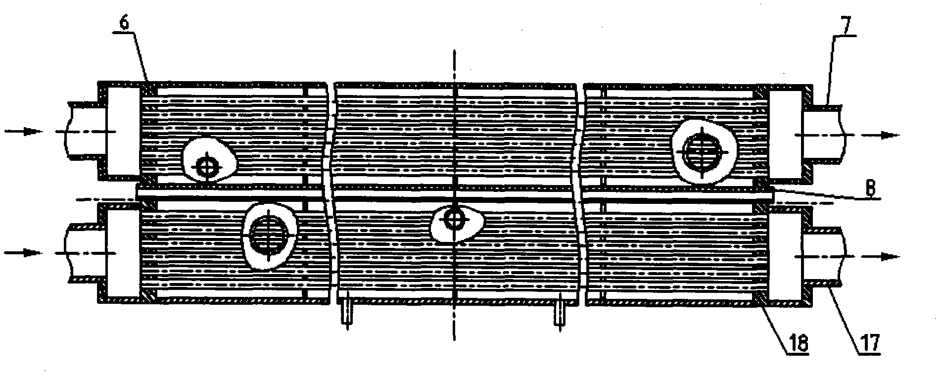
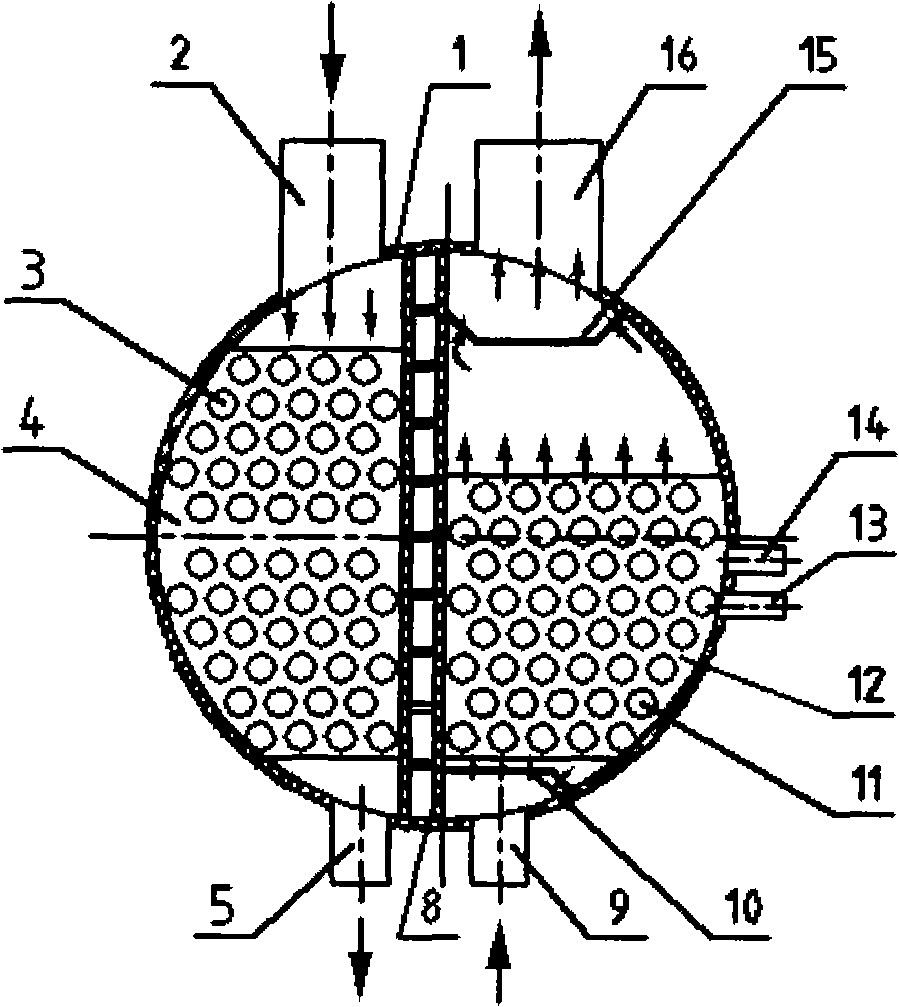
[0018] This embodiment is an integrated condensing flooded evaporator device used in a refrigeration and air-conditioning system with a heat load of 610kW and a cooling capacity of 510kW. The model is ELNRMZ470H. , condensing side support plate 4, refrigerant liquid outlet 5, condensing side tube plate 6, condensing side refrigerant inlet and outlet 7, double-layer partition plate 8, liquid inlet pipe 9, liquid separator 10, evaporator tube bundle 11, evaporator Side support plate 12, oil return low interface 13, oil return high interface 14, suction distributor 15, air outlet pipe 16, evaporating side refrigerant inlet and outlet 17 and evaporating side tube plate 18, each part is as attached figure 1 , 2 The given structure is installed, wherein: the outer diameter of the cylinder 1 is Φ516mm, the length is 3000mm, and it is made of steel plates; two vertical d...
PUM
Abstract
The invention relates to an integrated condensing flooded evaporator device and a using method thereof. A single condenser and a single flooded evaporator are adopted in the prior art, and the technical scheme is that: the condenser and the flooded evaporator are combined in the same cylinder. The device consists of a cylinder, an air inlet pipe, a condensing pipe bundle, a condensing side supporting plate, a refrigerant liquid outlet, a condensing side pipe plate, a condensing side secondary refrigerant inlet / outlet, a double-layer clapboard, a liquid inlet pipe, a dispenser, an evaporating pipe bundle, an evaporating side supporting plate, an oil return low interface, an oil return high interface, an air suction distributor, an air outlet pipe, an evaporating side secondary refrigerant inlet / outlet and an evaporating side pipe plate. The invention has the advantages that: two heat exchanger devices, namely the single condenser and the single flooded evaporator, are integrated in the same cylinder; and the device is compact in structure, saves pipelines, valves and raw materials by 20 percent, reduces pressure drop by 10 percent, reduces leakage points, wholly improves the energy efficiency by 8 to 10 percent, and is economic and energy-saving.
Description
technical field [0001] The invention relates to a heat exchange container device in a refrigerating and air-conditioning system, in particular to an integrated condensing flooded evaporator device in the refrigerating and air-conditioning system and its use method. Background technique [0002] The main components in the refrigeration and air conditioning system include: compressors, oil separators, condensers, liquid receivers, expansion valves, evaporators and other pipelines and electronic control equipment. The refrigeration cycle process is that the high-pressure superheated refrigerant and the refrigerated oil gas phase mixture discharged from the compressor pass through the oil separator for gas-liquid two-phase separation, and then the refrigerant enters the condenser and condenses into a high-pressure superheated refrigerant through the normal temperature refrigerant. The cold liquid, after throttling by the expansion valve, is vaporized in the evaporator through th...
Claims
Application Information
Patent Timeline
Application Date:The date an application was filed.
Publication Date:The date a patent or application was officially published.
First Publication Date:The earliest publication date of a patent with the same application number.
Issue Date:Publication date of the patent grant document.
PCT Entry Date:The Entry date of PCT National Phase.
Estimated Expiry Date:The statutory expiry date of a patent right according to the Patent Law, and it is the longest term of protection that the patent right can achieve without the termination of the patent right due to other reasons(Term extension factor has been taken into account ).
Invalid Date:Actual expiry date is based on effective date or publication date of legal transaction data of invalid patent.